HP StorageWorks Modular Smart Array 50 Storage Enclosure Maintenance and Service Guide April 2005 (First Edition) Part Number 379395-001
© Copyright 2005 Hewlett-Packard Development Company, L.P. The information contained herein is subject to change without notice. The only warranties for HP products and services are set forth in the express warranty statements accompanying such products and services. Nothing herein should be construed as constituting an additional warranty. HP shall not be liable for technical or editorial errors or omissions contained herein. Windows is a U.S. registered trademark of Microsoft Corporation. Linux is a U.S.
Contents Illustrated parts catalog 5 Customer self repair ............................................................................................................................. 5 System components.............................................................................................................................. 6 Removal and replacement procedures 7 Safety considerations .................................................................................................................
HP StorageWorks Modular Smart Array 50 Storage Enclosure Maintenance and Service Guide Acronyms and abbreviations 33 Index 37
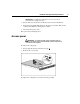
Illustrated parts catalog In this section Customer self repair........................................................................................................................5 System components ........................................................................................................................6 Customer self repair What is customer self repair? HP's customer self-repair program offers you the fastest service under either warranty or contract.
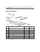
HP StorageWorks Modular Smart Array 50 Storage Enclosure Maintenance and Service Guide System components Item Description Spare part number Customer replaceable? 1 I/O module 377231-001 Yes 2 Rear panel LED board with cable (cable*) 377235-001 Yes 3 Fan 377233-001 Yes 4 AC power supply 377230-001 Yes 5 Fan board with cable and screw (cable and screw*) 377233-001 Yes 6 Midplane and backplane 377232-001 Yes 7 Power button/LED board with cable (cable*) 377236-001 Yes 8 2-m
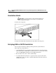
Removal and replacement procedures In this section Safety considerations......................................................................................................................7 Power down the storage enclosure .................................................................................................8 Access panel ...................................................................................................................................9 Hard drive blank ......................
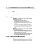
HP StorageWorks Modular Smart Array 50 Storage Enclosure Maintenance and Service Guide • Place parts on a grounded surface before removing them from their containers. • Avoid touching pins, leads, or circuitry. • Always be properly grounded when touching a static-sensitive component or assembly. Rack warnings WARNING: To reduce the risk of personal injury or damage to the equipment, be sure that: • The leveling jacks are extended to the floor.
Removal and replacement procedures IMPORTANT: If installing a hot-plug device, it is not necessary to power down the storage enclosure. 1. Power down any attached servers. Refer to the server documentation. 2. Press the Power On/Standby button on the storage enclosure. Wait for the system power LED to go from green to amber. 3. Disconnect the power cords. The system is now without power.
HP StorageWorks Modular Smart Array 50 Storage Enclosure Maintenance and Service Guide Hard drive blank CAUTION: To prevent improper cooling and thermal damage, do not operate the storage enclosure unless all bays are populated with either a component or a blank. To remove the component: To replace the blank, slide the blank into the bay until it locks into place. Hot-plug SAS or SATA hard drive You can replace hard drives without powering down the system.
Removal and replacement procedures 11 To minimize the likelihood of fatal system errors, take these precautions when removing failed drives: • Do not remove a degraded drive if any other drive in the array is offline (the Online LED is off). In this situation, no other drive in the array can be removed without data loss. Exceptions: – When RAID 1+0 is used, drives are mirrored in pairs.
HP StorageWorks Modular Smart Array 50 Storage Enclosure Maintenance and Service Guide 3. Remove the hard drive. To replace the component: 1. Slide the drive into the cage until it clicks, locking the drive into place. 2. Close the lever. IMPORTANT: When the drive is inserted, the drive LEDs flash for 2 seconds to indicate that the drive is seated properly and receiving power. 3.
Removal and replacement procedures To remove the component: 1. Disconnect the power cord from the power supply. 2. Remove the power supply. To replace the component, reverse the removal procedure. Hot-plug fan CAUTION: To prevent improper cooling and thermal damage, do not operate the storage enclosure unless all bays are populated with either a component or a blank.
HP StorageWorks Modular Smart Array 50 Storage Enclosure Maintenance and Service Guide To remove the component: To replace the component, reverse the removal procedure. I/O module CAUTION: To prevent improper cooling and thermal damage, do not operate the storage enclosure unless all bays are populated with either a component or a blank. To remove the component: 1. Power down the storage enclosure (on page 8). 2. Disconnect any SAS cables connected to the I/O module.
Removal and replacement procedures 15 3. Remove the I/O module. To replace the component, reverse the removal procedure. Midplane and backplane To remove the components: 1. Power down the storage enclosure (on page 8). 2. Remove the fan assembly ("Hot-plug fan" on page 13). 3. Remove all hot-plug power supplies ("Hot-plug power supply" on page 12). 4. Remove the I/O module ("I/O module" on page 14). 5. Remove all hard drives ("Hot-plug SAS or SATA hard drive" on page 10). 6.
HP StorageWorks Modular Smart Array 50 Storage Enclosure Maintenance and Service Guide 8. Disconnect all cables connected to the midplane. 9. Remove the midplane.
Removal and replacement procedures 10. Remove the backplane. Use the T-15 Torx screwdriver (on page 29). To replace the components, reverse the removal procedure. Fan board To remove the component: 1. Power down the storage enclosure (on page 8). 2. Remove the access panel ("Access panel" on page 9).
HP StorageWorks Modular Smart Array 50 Storage Enclosure Maintenance and Service Guide 3. Remove the fan board. Use the T-15 Torx screwdriver (on page 29). To replace the component, reverse the removal procedure. Rear panel LED board To remove the component: 1. Power down the storage enclosure (on page 8). 2. Remove the access panel ("Access panel" on page 9).
Removal and replacement procedures 19 3. Remove the rear panel LED board. Use the T-15 Torx screwdriver (on page 29). To replace the component, reverse the removal procedure. Power button/LED board To remove the component: 1. Power down the storage enclosure (on page 8). 2. Remove the access panel ("Access panel" on page 9).
HP StorageWorks Modular Smart Array 50 Storage Enclosure Maintenance and Service Guide 3. Remove the power button/LED board. Use the T-15 Torx screwdriver (on page 29). To replace the component, reverse the removal procedure.
Diagnostic tools In this section Integrated Management Log.........................................................................................................21 Array Diagnostic Utility ...............................................................................................................21 Integrated Management Log The IML records hundreds of events and stores them in an easy-to-view form. The IML timestamps each event with 1-minute granularity.
Component identification In this section Front panel LEDs and buttons ......................................................................................................23 Rear panel components.................................................................................................................24 Rear panel LEDs and buttons .......................................................................................................25 SAS and SATA drive numbers....................................
HP StorageWorks Modular Smart Array 50 Storage Enclosure Maintenance and Service Guide Item Description Status 2 Fault LED Off = No fault condition Amber = Fault condition 3 Heartbeat LED Green = System activity Off = No system activity 4 Power On/Standby button/LED Green = On Amber = Standby (auxiliary power present) Off = Off Rear panel components Item Description 1 SAS In connector 2 SAS Out connector 3 Power supply 1 4 Power supply 2 5 System fan
Component identification Rear panel LEDs and buttons Item Description Status 1 I/O module fault LED Green = No fault condition Power supply 1 LED Green = Power available 2 Amber = Fault condition Amber = Fault condition Off = Power supply unseated from connector or failed 3 Power supply 2 LED Green = Power available Amber = Fault condition Off = Power supply unseated from connector or failed 4 System fan LED Green = Normal operation Amber = Fault condition Off = Fan unseated from connector
HP StorageWorks Modular Smart Array 50 Storage Enclosure Maintenance and Service Guide Item Description Status 5 UID button/LED Blue = Identified Blue flashing = Active remote management Off = No active remote management 6 Fault LED Off = No fault condition Amber = Fault condition 7 Heartbeat LED Green = System activity Off = No system activity SAS and SATA drive numbers
Component identification SAS and SATA hard drive LEDs Item Description 1 Fault/ID LED (amber/blue) 2 Online LED (green) SAS and SATA hard drive LED combinations NOTE: Predictive failure alerts can occur only when the storage enclosure is connected to a Smart Array controller.
HP StorageWorks Modular Smart Array 50 Storage Enclosure Maintenance and Service Guide Online/Activity LED (green) Fault/UID LED (amber/blue) Interpretation Flashing regularly (1 Hz) Amber, flashing regularly (1 Hz) Do not remove the drive. Removing a drive may terminate the current operation and cause data loss. The drive is part of an array that is undergoing capacity expansion or stripe migration, but a predictive failure alert has been received for this drive.
Component identification 29 T-15 Torx screwdriver The storage enclosure includes a T-15 Torx screwdriver that ships inside the chassis. Use the screwdriver to loosen screws or thumbscrews, as needed, during service procedures.
Specifications In this section Environmental specifications .......................................................................................................31 Storage enclosure specifications...................................................................................................
HP StorageWorks Modular Smart Array 50 Storage Enclosure Maintenance and Service Guide Specification Value Width 42.62 cm (16.78 in) Weight (maximum) 16.78 kg (37 lb) Weight (no drives installed) 12.7 kg (27.
Acronyms and abbreviations ACU Array Configuration Utility ADG Advanced Data Guarding (also known as RAID 6) ADU Array Diagnostics Utility CSA Canadian Standards Association HBA host bus adapter IEC International Electrotechnical Commission IEEE Institute of Electrical and Electronics Engineers IML Integrated Management Log
HP StorageWorks Modular Smart Array 50 Storage Enclosure Maintenance and Service Guide ISEE Instant Support Enterprise Edition MSA Modular Smart Array MSA50 Modular Smart Array 50 NEC National Electrical Code NEMA National Electrical Manufacturers Association NFPA National Fire Protection Association ORCA Option ROM Configuration for Arrays OSEM Open Services Event Manager PSP ProLiant Support Pack
Acronyms and abbreviations RAID redundant array of inexpensive (or independent) disks RBSU ROM-Based Setup Utility SAS serial attached SCSI SATA serial ATA SCSI small computer system interface SFF small form-factor SIM Systems Insight Manager TMRA recommended ambient operating temperature UID unit identification WEBES Web-Based Enterprise Service 35
Index H hard drive blanks 10 hard drive LEDs 27 A AC power supply 24 access panel 9 ADU (Array Diagnostic Utility) 21 B blanks 10 buttons 23, 25 C component identification 23 connectors 24 CSR (customer self repair) 5 customer self repair 5 D diagnostic tools 21 drive bays 26 drive LEDs 27 E electrostatic discharge 7 enclosure LEDs 23, 25 environmental specifications 31 F fans 24 fault LED 23, 25 front panel buttons 23 front panel components 26 front panel LEDs 23 I illustrated parts catalog 5
HP StorageWorks Modular Smart Array 50 Storage Enclosure Maintenance and Service Guide S safety considerations 7, 8 SAS backplane 15 SAS drives 26 spare part numbers 6 specifications 31 static electricity 7 T temperature ranges (environmental) 31 tools 21, 29 Torx screwdriver 29 troubleshooting 27 U utilities 21 W warnings 8