HP StorageWorks 60 Modular Smart Array Enclosure User Guide November 2006 (Second Edition) Part Number 405868-002
© Copyright 2006 Hewlett-Packard Development Company, L.P. The information contained herein is subject to change without notice. The only warranties for HP products and services are set forth in the express warranty statements accompanying such products and services. Nothing herein should be construed as constituting an additional warranty. HP shall not be liable for technical or editorial errors or omissions contained herein. Microsoft and Windows are U.S. registered trademarks of Microsoft Corporation.
Contents Component identification ............................................................................................................... 6 Front panel LEDs and buttons ...................................................................................................................... 6 Rear panel components.............................................................................................................................. 7 Dual 7-segment display board...................................
Array Diagnostic Utility .................................................................................................................. 27 Remote support and analysis tools ............................................................................................................. 27 Open Services Event Manager ........................................................................................................ 27 Keeping the system current ...........................................................
Index.........................................................................................................................................
Component identification In this section Front panel LEDs and buttons ..................................................................................................................... 6 Rear panel components............................................................................................................................. 7 Rear panel LEDs and buttons .....................................................................................................................
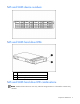
Rear panel components Item Description 1 Power supply 1 2 Fan module 1 3 Dual 7-segment display board (for box ID numbering) 4 SAS in connector 5 SAS out connector 6 I/O module bay 7 For future use 8 Fan module 2 9 Power supply 2 Dual 7-segment display board The dual 7-segment display board displays the host controller-assigned port and box ID number for the MSA60 to which it is connected. The host controller has two external ports.
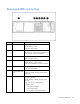
Rear panel LEDs and buttons Item Description Status 1 I/O module LED Green = System activity Amber flashing = Fault Off = No system activity 2 UID button/LED Blue = Identified Blue flashing = Active remote management Off = No active remote management 3 Heartbeat LED Green = System activity Off = No system activity 4 System fan LED Green = Normal operation Amber flashing = Fault condition Off = Fan unseated from connector or failed 5 System fault LED Amber = Fault condition Off = No fault c
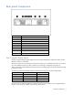
SAS and SATA device numbers SAS and SATA hard drive LEDs Item Description 1 Fault/UID LED (amber/blue) 2 Online LED (green) SAS and SATA hard drive LED combinations NOTE: Predictive failure alerts can occur only when the storage enclosure is connected to a Smart Array controller.
Online/activity LED Fault/UID LED (green) (amber/blue) Interpretation On, off, or flashing Alternating amber and blue The drive has failed, or a predictive failure alert has been received for this drive; it also has been selected by a management application. On, off, or flashing Steadily blue The drive is operating normally, and it has been selected by a management application. Amber, flashing regularly (1 Hz) A predictive failure alert has been received for this drive.
Operations In this section Power up............................................................................................................................................... 11 Power down the server............................................................................................................................ 11 Important Safety Information Before installing this product, read the Important Safety Information document provided.
2. Press the Power On/Standby button on the storage enclosure. Wait for the system power LED to go from green to amber. 3. Disconnect the power cords. The system is now without power.
Setup In this section Rack planning resources ......................................................................................................................... 13 Optimum environment............................................................................................................................. 13 Rack warnings ....................................................................................................................................... 15 Shipping contents.......................
When a vertical space in the rack is not filled by a server or rack component, the gaps between the components cause changes in airflow through the rack and across the servers. Cover all gaps with blanking panels to maintain proper airflow. CAUTION: Always use blanking panels to fill empty vertical spaces in the rack. This arrangement ensures proper airflow. Using a rack without blanking panels results in improper cooling that can lead to thermal damage.
• Do not allow the overall system AC current load to exceed 80 percent of the branch circuit AC current rating. • Do not use common power outlet strips for this equipment. • Provide a separate electrical circuit for each power supply in the storage enclosure. Electrical grounding requirements The storage enclosure must be grounded properly for proper operation and safety.
Rack mounting hardware kit contents The rack mounting hardware kit provides the required components for quick deployment in Compaq branded, HP branded, and most square- and round-hole third-party racks. The adjustable feature of the rack rails enables installation in racks with depths of 69.90 to 76.2 cm (27.52 to 30.00 in). If you are installing the MSA60 in an M-Series rack, contact an authorized reseller to obtain an M-Series Rack Rail option kit.
3. Use a No. 2 Phillips screwdriver to remove the standard pins from the front and back ends of the rail. 4. Install four round-hole pins into the rail. 5. Repeat steps 3 and 4 for the second rail. Installing a storage enclosure into the rack To install the storage enclosure into the rack: 1. Secure the front end of the rails to the rack. IMPORTANT: Do not remove the pins from the ends of the rack rails unless you are converting the rails for use in round-hole racks.
NOTE: Identify the left (L) and right (R) rack rails by markings stamped into the sheet metal. 2. Secure the back end of the rails to the rack. IMPORTANT: Be sure that the scissor-type locking latches engage the rack fully when the pins extend through the holes marked with the template. 3. Slide the chassis into the rack. 4. Use the thumbscrews on the front of the chassis to secure it to the rack. 5.
If you are installing the storage enclosure into a telco rack, order the appropriate option kit at the RackSolutions website (http://www.racksolutions.com/hp). Follow the storage enclosure-specific instructions on the website to install the rack brackets. Use the following information when connecting peripheral cables and power cords to the storage enclosure.
Choosing a configuration Cable procedures vary, depending on the configuration. Choose one of the following configurations. NOTE: The left connector of the I/O module is for input from the server. The right connector of the I/O module is for output to another storage enclosure. See the icons on the cables and enclosure to assist in proper connection.
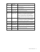
Cascading (1+1) configuration Item Description 1 MSA60 1* 2 MSA60 2* 3 SAS cable 4 SAS cable 5 Server * Only MSA60 enclosures can be cascaded. Do not configure with other types of storage enclosures.
For a complete list of supported cables, see the QuickSpecs on the HP website (http://www.hp.com). Power cords The power cord should be approved for use in your country. The power cord must be rated for the product and for the voltage and current marked on the electrical ratings label of the product. The voltage and current rating for the cord should be greater than the voltage and current rating marked on the product. In addition, the diameter of the wire must be a minimum of 1.
Hardware options installation In this section Hard drive options ................................................................................................................................. 23 Hard drive options The storage enclosure supports up to 12 SAS or SATA hard drives. Always populate hard drive bays starting with the lowest device number ("SAS and SATA device numbers" on page 9).
2. Prepare the hard drive. 3. Install the hard drive. IMPORTANT: When the drive is inserted, the drive LEDs flash for 2 seconds to indicate that the drive is seated properly and receiving power. 4. Determine the status of the hard drive from the SAS and SATA hard drive LED combinations.
Configuration and utilities In this section Configuration tools ................................................................................................................................. 25 Management tools.................................................................................................................................. 26 Diagnostic tools .....................................................................................................................................
For more information regarding array controller configuration, refer to the controller user guide. For more information regarding the default configurations that ORCA uses, refer to the HP ROM-Based Setup Utility User Guide on the Documentation CD. Smart Components for ROM Flash To update the firmware on the server, controller, hard drives, or enclosure use Smart Components. These components are available on the Firmware Maintenance CD.
• From within Survey Utility • From within operating system-specific IML viewers • For NetWare: IML Viewer • For Windows®: IML Viewer • For Linux: IML Viewer Application • From within the iLO user interface • From within HP Insight Diagnostics For more information, refer to the Management CD in the HP ProLiant Essentials Foundation Pack. Array Diagnostic Utility The HP Array Diagnostics Utility is a web-based application that creates a report of all HP storage controllers and disk drives.
Troubleshooting In this section When the storage enclosure does not start ................................................................................................ 28 Diagnostic questions ............................................................................................................................... 29 Recognizing hard drive failure.................................................................................................................
Diagnostic questions Are the power supply/system fan LEDs green? Answer Possible Reasons No • The power cords are not connected or AC power is not available. • Be sure that the power cord is connected to the power supply. • The power supply may not be inserted properly, it may have a damaged connector, or it may have failed. • Be sure that the power supply is undamaged and is fully seated. • The system midplane may need to be replaced.
For additional information about diagnosing hard drive problems, see the HP ProLiant Servers Troubleshooting Guide. CAUTION: Sometimes, a drive that has previously failed may seem to be operational after the system is power-cycled or (for a hot-pluggable drive) after the drive has been removed and reinserted. However, continued use of such marginal drives may eventually result in data loss. Replace the marginal drive as soon as possible.
• Open HP SIM and inspect the Error Counter window for each physical drive in the same array to confirm that no other drives have any errors. (For details, refer to the HP SIM documentation on the Management CD.) • Be sure that the array has a current, valid backup. • Use replacement drives that have a capacity at least as great as that of the smallest drive in the array. The controller immediately fails drives that have insufficient capacity.
• The amount of unused capacity on the drives • The number of drives in the array (for RAID 5 and RAID 6 with ADG) Allow approximately 15 minutes per gigabyte for the rebuild process to be completed. This figure is conservative, and newer drive models usually require less time to rebuild. System performance is affected during the rebuild, and the system is unprotected against further drive failure until the rebuild has finished. Therefore, replace drives during periods of low activity when possible.
Some status messages are available without pressing the F3 key. For example, on the Main menu, the FAILED status appears next to the logical drive that has failed. EXPANDING and REBUILDING appear next to the array in which the activity is occurring. Handling disk drive failures If the controller was configured with hardware fault tolerance, complete the following steps after a disk drive failure: 1. Determine which physical drive failed. On hot-plug drives, an amber drive failure LED illuminates. 2.
Regulatory compliance notices In this section Regulatory compliance identification numbers ........................................................................................... 34 Federal Communications Commission notice ............................................................................................. 34 Declaration of conformity for products marked with the FCC logo, United States only..................................... 35 Modifications...................................................
Class A equipment This equipment has been tested and found to comply with the limits for a Class A digital device, pursuant to Part 15 of the FCC Rules. These limits are designed to provide reasonable protection against harmful interference when the equipment is operated in a commercial environment. This equipment generates, uses, and can radiate radio frequency energy and, if not installed and used in accordance with the instructions, may cause harmful interference to radio communications.
Modifications The FCC requires the user to be notified that any changes or modifications made to this device that are not expressly approved by Hewlett-Packard Company may void the user’s authority to operate the equipment. Cables Connections to this device must be made with shielded cables with metallic RFI/EMI connector hoods in order to maintain compliance with FCC Rules and Regulations.
Disposal of waste equipment by users in private households in the European Union This symbol on the product or on its packaging indicates that this product must not be disposed of with your other household waste. Instead, it is your responsibility to dispose of your waste equipment by handing it over to a designated collection point for the recycling of waste electrical and electronic equipment.
Korean notice Class A equipment Class B equipment Power cord statement for Japan Regulatory compliance notices 38
Electrostatic discharge In this section Preventing electrostatic discharge............................................................................................................. 39 Grounding methods to prevent electrostatic discharge ................................................................................ 39 Preventing electrostatic discharge To prevent damaging the system, be aware of the precautions you need to follow when setting up the system or handling parts.
Specifications In this section Environmental specifications .................................................................................................................... 40 Storage enclosure specifications ..............................................................................................................
Technical support In this section Before you contact HP............................................................................................................................. 41 HP contact information............................................................................................................................ 41 Customer Self Repair ..............................................................................................................................
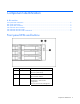
• Mandatory—Parts for which customer self repair is mandatory. If you request HP to replace these parts, you will be charged for the travel and labor costs of this service. • Optional—Parts for which customer self repair is optional. These parts are also designed for customer self repair. If, however, you require that HP replace them for you, there may or may not be additional charges, depending on the type of warranty service designated for your product.
Pour plus d'informations sur le programme CSR de HP, contactez votre Mainteneur Agrée local. Pour plus d'informations sur ce programme en Amérique du Nord, consultez le site Web HP (http://www.hp.com/go/selfrepair). Riparazione da parte del cliente Per abbreviare i tempi di riparazione e garantire una maggiore flessibilità nella sostituzione di parti difettose, i prodotti HP sono realizzati con numerosi componenti che possono essere riparati direttamente dal cliente (CSR, Customer Self Repair).
CSR-Teile werden abhängig von der Verfügbarkeit und vom Lieferziel am folgenden Geschäftstag geliefert. Für bestimmte Standorte ist eine Lieferung am selben Tag oder innerhalb von vier Stunden gegen einen Aufpreis verfügbar. Wenn Sie Hilfe benötigen, können Sie das HP technische Support Center anrufen und sich von einem Mitarbeiter per Telefon helfen lassen. Den Materialien, die mit einem CSRErsatzteil geliefert werden, können Sie entnehmen, ob das defekte Teil an HP zurückgeschickt werden muss.
Customer Self Repair Veel onderdelen in HP producten zijn door de klant zelf te repareren, waardoor de reparatieduur tot een minimum beperkt kan blijven en de flexibiliteit in het vervangen van defecte onderdelen groter is. Deze onderdelen worden CSR-onderdelen (Customer Self Repair) genoemd.
Conforme a disponibilidade e o local geográfico, as peças CSR serão enviadas no primeiro dia útil após o pedido. Onde as condições geográficas permitirem, a entrega no mesmo dia ou em quatro horas pode ser feita mediante uma taxa adicional. Se precisar de auxílio, entre em contato com o Centro de suporte técnico da HP para que um técnico o ajude por telefone. A HP especifica nos materiais fornecidos com a peça CSR de reposição se a peça com defeito deve ser devolvida à HP.
Technical support 47
Technical support 48
Acronyms and abbreviations ACU Array Configuration Utility ADG Advanced Data Guarding (also known as RAID 6) ADU Array Diagnostics Utility CSA Canadian Standards Association HBA host bus adapter IEC International Electrotechnical Commission IEEE Institute of Electrical and Electronics Engineers IML Integrated Management Log MSA Modular Smart Array MSA60 Modular Storage Array 60 NEC National Electrical Code NEMA National Electrical Manufacturers Association Acronyms and abbreviations 49
NFPA National Fire Protection Association ORCA Option ROM Configuration for Arrays OSEM Open Services Event Manager PSP ProLiant Support Pack RAID redundant array of inexpensive (or independent) disks RBSU ROM-Based Setup Utility SAS serial attached SCSI SATA serial ATA SCSI small computer system interface SFF small form-factor SIM Systems Insight Manager TMRA recommended ambient operating temperature UID unit identification Acronyms and abbreviations 50
Index A ADU (Array Diagnostic Utility) 27 airflow requirements 13 Array Diagnostic Utility (ADU) 27 authorized reseller 41 B BSMI notice 37 buttons 6 C cables 36 Care Pack 27 Change Control 27 component identification 6, 7 components 6, 7 compromised fault tolerance 30 configuration 20 configuration of system 25 configuration tools 25 connectors 6 contacting HP 41 CSR (customer self repair) 41 customer self repair (CSR) 41 D Declaration of Conformity 35 diagnostic tools 26 drive failure, detecting 32 E
O telephone numbers 41 temperature requirements 14 troubleshooting 9, 28 Open Services Event Manager 27 optimum environment 13 Option ROM Configuration for Arrays (ORCA) 25 options installation 23 ORCA (Option ROM Configuration for Arrays) 25 U P W phone numbers 41 power cord 22, 38 power requirements 14 powering up 11 problem diagnosis 28 warnings 15 utilities 25 R rack installation 15 rack mounting hardware 15 rack resources 13 rack warnings 15 rear panel buttons 8 rear panel components 7 rear pa