HP StoreEver MSL6480 Tape Library Getting Started Guide Abstract This guide provides information on installing the tape library. This guide is intended for system administrators and other users who need physical knowledge of the tape library.
© Copyright 2013, 2014 Hewlett-Packard Development Company, L.P.
Contents 1 Overview..................................................................................................4 Front panel overview.................................................................................................................4 Back panel overview.................................................................................................................4 Tape drive back panel overviews.............................................................................................
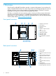
1 Overview The HP StoreEver MSL6480 Tape Library provides a compact, high-capacity, low-cost solution for simple, unattended data backup. This unique design houses up to 80 tape cartridges for each 6U of height, with easy access to tape cartridges via removable mailslots. The library is customer expandable with expansion modules and exchangeable tape drives. The library is compatible with most operating systems.
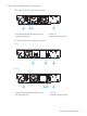
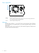
Tape drive back panel overviews SAS tape drive back panel overview 1 2 3 4 1. Tape drive Ethernet port (reserved for future use) 2. SAS port A 3. SAS port B (LTO-6 only) 4. Tape drive power LED, green FC tape drive back panel overviews LTO-5 1 2 4 LTO-6 1 2 3 4 1. Tape drive Ethernet port (reserved for future use) 2. FC port A 3. FC port B (LTO-6 only) 4.
Power supply LEDs 1 2 3 1. White AC power is connected. 2. Amber The power supply has experienced a fault condition, such as the fan not running, temperature too hot, or producing power that is outside specifications. 3. Green The power supply is operating correctly. USB ports The library has two USB ports — one on the OCP and one on the back panel. With a USB thumb drive in the USB port, you can update firmware, save or restore configuration settings, or download support tickets.
Element numbering Modules, tape drives, and storage slots are numbered from the bottom of the library up, starting with one. 3 10 9 6 2 8 7 5 4 3 1 2 1 Storage slots and mailslot elements are numbered as shown. 50 2 80 40 10 41 31 50 71 70 1 1 1. Left magazine 41 61 3 MS10 MS1 2. Right magazine with the mailslot disabled 3.
Library user interfaces • Remote management interface (RMI) — this interface lets you monitor and control the library from a web page. You can access most library functions from the RMI. • Operator control panel (OCP) — this interface lets you operate the device from the front panel. Status icons The green Status OK icon indicates that the library is fully operational and that no user interaction is required.
Logging in Using the OCP, find the library IP address on the home screen. Open any HTML web browser and enter the library IP address. Select the account type. Enter the password if one has been set. Click Sign In. TIP: Once signed in, click Help in the upper right-hand corner for more information about the fields and information available in the RMI.
2 Planning the installation Pre-installation checklist • Choose a location for the library. See “Choosing a location” (page 10). • Plan the rack layout. See “Planning the module and rack layout” (page 11). • Plan the FC or SAS configuration and obtain necessary cables. See “Planning the Fibre Channel configuration” (page 11) or “Planning the SAS configuration” (page 12). • Plan partitioning. See “Planning partitioning into logical libraries” (page 12).
Planning the module and rack layout When possible, install the base module near the middle of the rack at a convenient height for viewing and operating the OCP and accessing the mailslot. If the library will be sharing the rack with other equipment, place heavy devices, such as disk arrays, in the bottom of the rack to reduce the chance of the rack tipping. The library supports up to three expansion modules above and three modules below the base module, for a total of seven modules. Each module occupies 6U.
Planning the SAS configuration WARNING! Only HP SAS RAID controllers are supported for use with the library. For supported controllers see the EBS compatibility matrix at: http://www.hp.com/go/ebs. Seuls les contrôleurs RAID SAS de HP sont compatibles avec la bibliothèque. Pour connaître les contrôleurs pris en charge, consultez la matrice de compatibilité EBS à l'adresse : http://www.hp.com/go/ebs. Most SAS HBA ports have four SAS channels.
For ease of use and optimal performance, HP recommends that the logical libraries be configured as simply as possible, and that the flexibility be used to adjust logical library capacity as the organization requirements change. • Assign groups of contiguous slots to each logical library. • Locate the slots and drives for a logical library near each other, ideally within the same module.
3 Installing the library WARNING! Each library module weighs 41 kg (90 lb) without media or tape drives and 71.4 kg (157.4 lb) with media (80 cartridges) and six tape drives. When moving the library, to reduce the risk of personal injury or damage to the device: • Observe local health and safety requirements and guidelines for manual material handling. • Remove all tapes to reduce the overall weight of the device and to prevent cartridges from falling into the robotic path and damaging the library.
Preparing the host IMPORTANT: Use proper procedures to prevent electrostatic discharge (ESD). Use wrist-grounding straps and anti-static mats when handling internal components. • Check with the system administrator before powering off the host computer. • For a SAS library, install a SAS HBA with an external SAS connector that supports multiple LUNs. Refer to the manuals for the host computer and the HBA for installation information.
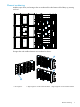
The base module has removable top and bottom covers. You will need to transfer one or both covers from the base module to expansion modules. The covers are identical and the procedure to change them is the same for both top and bottom covers. 16 • If you are installing expansion modules below the base library, move the bottom cover from the base library to the expansion module that will be installed at the bottom of the library.
To move a library cover plate from the base module to an extension module: 1. Remove the library cover plate from the base module. a. Place the base module on a work table. If you are removing the bottom cover, gently turn the base module over so you can access the bottom of the module. b.
2. Install the cover on the expansion module. a. Place the expansion module on the work table. If the module will be the bottom module in the library, gently turn the module over so you can access the bottom of the module. b. Align all eight tabs on the cover with the slots on the module, gently push it down, and then slide the cover towards the back of the module until the spring lock at the front of the module engages by popping out. c.
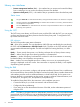
2. From the front of the rack, insert the rack rails into the back and then front vertical supports. a. Position a rail according to the left-right front-rear orientation information stamped on the rail. b. Rotate the front of the rail up while inserting the rear rail hanger into the middle hole of the marked U section in the rear vertical support, and then lower the front of the rail until it is nearly level. c.
3. On the front of both rails in a square-hole rack, install a clip nut above the mounting bracket as shown For increased stability, install the retention inserts from the packet labeled Retention inserts using a T10 Torx driver. 1 2 4 3 The library has a three-part rail system: • Outer rail is installed in the rack. • Middle rail connects to the inner and outer rails so the module can be slid out of the rack. • Inner rail is attached to the module.
2. Slide the inner rails into the middle rails. Slide the module into the rack. a. Once the module is secure on the rails, remove the protective tape on the front of the module around the thumbscrews. b. Depress the release clips on both rails and then slide the module completely into the rack. If the module does not go fully into the rack the first time, pull the module back out to the lock position and insert it again. 2 3.
Verify that the gap between modules is less than 4mm on both sides of the front of the modules. The gap in the back must be less than 5mm. If the gap is larger or varies side to side: • Confirm that both rack rails are properly located within the U volume. • Confirm that both rack rails are properly seated in the rack vertical column. • Verify that the top hanger for the rear of each rack rail is in the middle hole of the marked U section. • Check the rack vertical columns for bending.
Aligning and connecting modules Skip this step if the library does not have expansion modules. Aligning the modules ensures that the robot can move freely between the modules. The library will not operate unless the alignment mechanism is in the locked position. CAUTION: Do not use the alignment mechanism to force the modules into alignment. The alignment mechanism is designed to hold the modules in position once they are aligned, but is not intended to adjust the module positions.
3. 4. 5. Verify that the lowest module in the library has its alignment mechanism secured in the unlocked position with the thumbscrew. From the front of the library, use your fingers to tighten the thumbscrews on each of the modules to secure the modules to the rack. From the back of the library connect the lower module of each pair to its adjacent module using the expansion interconnect cable as shown.
Connecting the Fibre Channel cables 1. Remove the FC port caps if necessary. Attach one end of the FC cable to port A on the tape drive. 2. Attach the other end of the FC cable to a switch or HBA. NOTE: Using both ports on a dual-port drive requires multi-path capability in the host application. Refer to the application documentation for information on configuring the second port. Connecting the SAS cable 1. 2. Attach the HBA end of the SAS cable into the connector on the HBA.
Powering on the library Plug the power cables into the power connectors on each module and into power outlets. TIP: The library has dual redundant power supplies. To increase redundancy, plug each power cord into a different AC power circuit. To use the RMI, connect an Ethernet cable from the Ethernet port on the library module controller to your network. 1 2 1. Power connectors 2.
Labeling and loading the tape cartridges The library will power on without cartridges, but needs cartridges before performing data read and write operations, or any tests or operations that transfer cartridges. For proper operation, use barcode labels in production environments. The library does not support the use of media without barcode labels. Using the mailslot If the mailslot is enabled, you can use it to load cartridges into the library.
4. Repeat steps 1 through 3 for each of the other magazines. Verifying the installation Verify that the library has the current firmware revision. The library firmware revision is displayed in the top left corner of the OCP and RMI screen. If necessary, update the library firmware from the OCP or RMI Maintenance > Software Upgrades > System Firmware screen.
4 Support and other resources Contacting HP For worldwide technical support information, see the HP support website: http://www.hp.
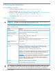
A Technical specifications and regulatory information Table 3 Physical specifications Characteristic Product alone Packaged Height 268 mm 615 mm Width 475 mm 800 mm Depth 892 mm 1200 mm Weight Base module: 41.0 Kg Base module: 54.5 Kg Expansion module: 36.50 Kg Expansion module: 50.0 Kg Each module is shipped on a wooden pallet. Pallets may be stacked three high.
B Regulatory information For important safety, environmental, and regulatory information, see Safety and Compliance Information for Server, Storage, Power, Networking, and Rack Products, available at http:// www.hp.com/support/Safety-Compliance-EnterpriseProducts. Regulatory compliance identification numbers For the purpose of regulatory compliance certifications and identification, this product has been assigned a unique regulatory model number.
Local Representative information Kazakh: • HP Kazakhstan: ЖШС «Хьюлетт-Паккард (К)», Қазақстан, Алматы қ., Бостандық ауданы, Тимирязев к-сі, 28В, тел./факс: +7 (727) 355 35 50, +7 (727) 355 35 51 Manufacturing date: The manufacturing date is defined by the serial number.