HP MSR1000 Router Installation Guide Part number: 5998-4997 Document version: 6W100-20131218
Legal and notice information © Copyright 2013 Hewlett-Packard Development Company, L.P. No part of this documentation may be reproduced or transmitted in any form or by any means without prior written consent of Hewlett-Packard Development Company, L.P. The information contained herein is subject to change without notice.
Contents Preparing for installation ············································································································································· 1 Safety recommendations ·················································································································································· 1 Safety symbols ·················································································································································
Garbled terminal display······································································································································ 28 No response from the serial port ························································································································· 28 Restoring the factory settings ········································································································································ 28 Scenario 1 ··········
Preparing for installation The HP MSR1000 routers include the following models: MSR1003-8. Table 1 Models in The HP MSR1000 Router Series Series Product Code HP Description RMN MSR1000 JG732A HP MSR1003-8 Router BJNGA-BB0029 IMPORTANT: For regulatory identification purposes, every MSR1000 router is assigned a regulatory model number (RMN). These regulatory model numbers should not be confused with the marketing name HP MSR1000, or products codes.
Examining the installation site The router must be used indoors. To ensure correct operation and long service life of your router, the installation site must meet the following requirements. Temperature and humidity You must maintain a compliant temperature and humidity in the equipment room. • Lasting high relative humidity tends to cause poor insulation, electricity creepage, mechanical property change of materials, and corrosion of metal parts.
Cooling system The MSR1000 router adopts left to right airflow for heat dissipation. Figure 1 Airflow through the MSR1000 chassis To ensure good ventilation, the following requirements must be met: • Leave at least 10 cm (3.94 in) of clearance at the air inlet and outlet vents. • The installation site has a good cooling system. ESD prevention CAUTION: Check the resistance of the ESD wrist strap for safety.
EMI Electromagnetic interference (EMI) might be coupled from the source to the router through the following coupling mechanisms: • Capacitive coupling • Inductive coupling • Radiative coupling • Common impedance coupling • Conductive coupling To prevent EMI, take the following actions: • Take effective measures to reduce interference from the power grid system. • Separate the router grounding equipment from grounding and lightning protection equipment of other devices as far as possible.
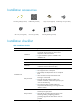
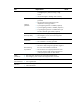
Installation accessories Grounding cable (provided) M6 screw (user supplied) Rubber feet (provided) Cage nut (user supplied) M4 screw (provided) Load-bearing screw (provided) Mounting brackets (provided) Installation checklist Table 5 Installation checklist Item Requirements • There is a minimum clearance of 10 cm (3.94 in) Ventilation around the inlet and outlet air vents for heat dissipation of the router chassis. • A good ventilation system is available at the installation site.
Item Requirements • Keep the router far away from radio stations, radar and high-frequency devices working in high current. • Use electromagnetic shielding when necessary. • The grounding cable of the chassis is correctly grounded. • The grounding terminal of the AC power Lightning protection receptacle is correctly grounded. • A port lightning arrester is installed. (Optional.) • A power lightning arrester is installed. (Optional.
Installing the router WARNING! To avoid injury, do not touch bare wires, terminals, or parts with high-voltage hazard signs. IMPORTANT: • The barcode on the router chassis contains product information that must be provided to local sales agent before you return a faulty router for service. • Keep the tamper-proof seal on a mounting screw on the chassis cover intact, and if you want to open the chassis, contact HP for permission. Otherwise, HP shall not be liable for any consequence.
Figure 2 Installation flow Start Mount the router on a workbench Mount the router in a rack Determine the installation position Mount the router on a workbench Mount the router in a rack Ground the router Install interface modules Connect interface cables Connect the router to a terminal Connect the power cord Verify the installation Power on the router Troubleshoot the router Operating correctly? Power off the router No Yes End 8
Installing the router Mounting the router on a workbench IMPORTANT: • Allow 10 cm (3.94 in) of clearance around the chassis for heat dissipation. • Do not place heavy objects on the router. To mount the router on a workbench: 1. Make sure the workbench is clean, stable, and correctly grounded. 2. Place the router upside down on the workbench and attach the rubber feet to the four round holes in the chassis bottom. Figure 3 Attaching the rubber feet 3.
To install the router in a rack: 1. Use a mounting bracket to mark the positions of cage nuts on the front rack posts, making sure the cage nuts on the two front rack posts are at the same level. Figure 5 Marking the positions of cage nuts 2. Insert one edge of a cage nut into the hole. Use a flat-blade screwdriver to compress the other edge of the cage nut, and then push the cage nut fully into the hole. 3. Repeat step 3 to install other cage nuts to all the marked positions on the front rack posts.
Figure 6 Installing cage nuts 4. Attach the mounting brackets to the two sides of the chassis and fasten the screws. Figure 7 Attaching the mounting brackets 5. Place the chassis on the rack and use M6 screws to attach the mounting brackets to the rack posts.
Figure 8 Securing the router to the rack Grounding the router WARNING! Correctly connecting the router grounding cable is crucial to lightning protection and EMI protection. IMPORTANT: The resistance reading should be smaller than 5 ohms between the chassis and the ground. Grounding the router through the rack IMPORTANT: Make sure the rack is correctly grounded before grounding the router. To connect the grounding cable: 1. Remove the grounding screw from the grounding hole at the rear of the chassis.
4. Use needle-nose pliers to bend a hook at the other end of the grounding cable, attach it to the grounding post, and reinstall the hex nut. See Figure 9.
1 2 Grounding the router with a grounding strip If a grounding strip is available at the installation site, connect the grounding cable to the grounding strip. Follow the same procedures in "Grounding the router through the rack" to connect the grounding cable.
Figure 10 Grounding the router with a grounding strip 1 2 Grounding the router with a grounding conductor buried in the earth ground If the installation site has no grounding strips, but earth ground is available, hammer a 0.5 m (1.64 ft) or longer angle iron or steel tube into the earth ground to serve as a grounding conductor. The steel tube must be zinc-coated. Weld the yellow-green grounding cable to the angel iron or steel tube and treat the joint for corrosion protection.
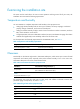
Figure 11 Removing the blank filler panel Figure 12 Installing the SIC Installing a DSIC CAUTION: DSIC interface modules are not hot swappable. Make sure the router is powered off before installing a DSIC. To install a DSIC: 1. Remove the screws on the filler panel on slot 1 and slot 2 of the router to remove the filler panel, as shown in Figure 13. 2. Loosen the captive screws on the slot divider and pull out the slot divider, as shown in Figure 14.
Figure 14 Removing the slot divider 3. Insert the DSIC into the slot and push it along the slide rails until it makes close contact with the backplane of the router. Figure 15 Installing a DSIC 4. Fasten the captive screws to secure the DSIC. Connecting interface cables Connect interface cables before powering on the router. This section describes how to connect Ethernet cables. For other cable connection methods, see HP MSR Series Routers Interface Module User Guide. To connect an Ethernet cable: 1.
Figure 16 Connecting the router to a PC Logging in through the console port Connecting a console cable IMPORTANT: When you connect a PC to a powered-on router, connect the RJ-45 connector to the router after connecting the DB-9 connector of the console cable to the PC. To connect a console cable: 1. Plug the DB-9 female connector to the serial port of the configuration terminal. 2. Connect the RJ-45 connector to the console port of the router.
Figure 18 Connection description 2. Select the serial port to be used from the Connect using list, and click OK. Figure 19 Setting the serial port used by the HyperTerminal connection 3. Set Bits per second to 9600, Data bits to 8, Parity to None, Stop bits to 1, and Flow control to None, and click OK. 4. To restore the default settings, click Restore Defaults.
Figure 20 Setting the serial port parameters 5. Select File > Properties in the HyperTerminal window. Figure 21 HyperTerminal window 6. On the Settings tab, set the emulation to VT100 or Auto detect and click OK.
Figure 22 Setting terminal emulation in test Properties dialog box Connecting an AC power cord 1. Make sure the router is correctly grounded, and the power switch on the router is in the OFF position. 2. Connect one end of the AC power cord to the AC receptacle on the router, and the other end to the AC power source. 3. Install the bail latch and push it leftward to secure the power cord.
Figure 23 Connecting an AC power cord to the router 1 2 Verifying the installation After you complete the installation, verify that: • There is enough space for heat dissipation around the router, and the rack or workbench is stable. • Interface modules are correctly installed. • The router, rack, and power cord are correctly grounded. • The correct power source is used.
Powering on the router 1. Turn on the switch of the power supply system for the router. 2. Turn on the switch of the AC or DC power modules. Displaying boot information Power on the router, and you can see the following information: System is starting... Press Ctrl+D to access BASIC-BOOTWARE MENU Booting Normal Extend BootWare The Extend BootWare is self-decompressing...................................
Examining the router after power-on After the router is powered on, verify that: • The LEDs on the front panel are operating correctly: LED Status Description PWR Steady green The power module is supplying power correctly. SYS Slow flashing green The router is operating correctly. • The configuration terminal displays information correctly. For local configuration, the configuration terminal displays the boot information (see "Displaying boot information").
Replacement procedure CAUTION: SIC and DSIC interface modules are not hot swappable. Make sure the router is powered off before installing a SIC or DSIC. Replacing a SIC 1. Loosen the captive screws on the SIC interface module. 2. Gently pull the SIC interface module out along the slide rails. 3. Install a new SIC interface module. For the installation procedure, see "Installing the router." If you do not install a SIC interface module, install a blank filler panel and tighten the screws.
If you need to install SIC or DSIC interface modules, see "Installing the router" for the installation procedure. To install filler panels, proceed to steps 3 and 4. 3. Gently push the slot divider into the DSIC slot along the slide rails and tighten the screws. 4. Install the filler panels and tighten the screws.
Troubleshooting IMPORTANT: • The barcode on the router chassis contains product information that must be provided to local sales agent before you return a faulty router for service. • Keep the tamper-proof seal on a mounting screw on the chassis cover intact, and if you want to open the chassis, contact HP for permission. Otherwise, HP shall not be liable for any consequence. Power supply failure If the router cannot be powered on and LEDs on the front panel are off, the power supply is faulty.
Garbled terminal display If terminal display is garbled, make sure the Data bits field for the console terminal is set to 8. If the Data bits field is set to 5 or 6, the console terminal will display garbled characters. No response from the serial port If the serial port does not respond, verify that the serial cable is in good condition and the serial port settings are correct. Restoring the factory settings Scenario 1 Symptom When you replace the router, the router password is lost.
Reset button usage guidelines An MSR1000 router provides the Reset button. You can use the button to reboot the system or restore the factory settings. 1. Press the Reset button for a short time to reboot the router. 2. Press the Reset button for more than 4 seconds to reboot the router and restore the factory settings.
Appendix A Chassis views and technical specifications Chassis views The following figures are for illustration only.
Item MSR1003-8 Memory 512 MB DDR3 Flash 256 MB SIC/DSIC slot 3 SIC slots (1 DSIC slot) Dimensions (H × W × D) (excluding rubber feet and mounting brackets) 44.2 × 360 × 300 mm (1.74 × 14.17 × 11.
Appendix B LEDs Panel LEDs Figure 31 MSR1003-8 LEDs (1) System LED (SYS) (2) Power supply LED (PWR) (3) Gigabit Ethernet port LED (GE0 to GE9) LED description LED SYS PWR GE State Description Flashing green (1 Hz) Comware has started with the configuration file and the router has booted up. Flashing green (8 Hz) The BootWare runs. Steady green The SDRAM is performing self-test. Flashing yellow (1 Hz) The DDR3 SDRAM has failed the self-test.
Appendix C Slot arrangement The MSR1003-8 router provides slots for SICs. A DSIC can be installed if you remove the slot divider between two SIC slots. The slot number of fixed ports on the MSR1003-8 router is 0..
Support and other resources Contacting HP For worldwide technical support information, see the HP support website: http://www.hp.
Conventions This section describes the conventions used in this documentation set. Command conventions Convention Description Boldface Bold text represents commands and keywords that you enter literally as shown. Italic Italic text represents arguments that you replace with actual values. [] Square brackets enclose syntax choices (keywords or arguments) that are optional. { x | y | ... } Braces enclose a set of required syntax choices separated by vertical bars, from which you select one.
Network topology icons Represents a generic network device, such as a router, switch, or firewall. Represents a routing-capable device, such as a router or Layer 3 switch. Represents a generic switch, such as a Layer 2 or Layer 3 switch, or a router that supports Layer 2 forwarding and other Layer 2 features. Represents an access controller, a unified wired-WLAN module, or the switching engine on a unified wired-WLAN switch. Represents an access point.
Index CDEGILMNPRSTVW C M Cleanness,2 Mounting the router on a workbench,9 Connecting a console cable,18 N Cooling system,3 No response from the serial port,28 D No terminal display,27 Displaying boot information,23 P Documents,34 Powering on the router,23 E R Electricity safety,1 Rack-mounting,4 EMI,4 Reset button usage guidelines,29 ESD prevention,3 Examining the router after power-on,24 S G Safety symbols,1 Scenario 1,28 Garbled terminal display,28 Scenario 2,28 General safety re