
HP MSR1000 Router Series Installation Guide

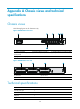

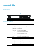
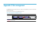
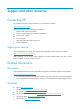
Table Of Contents
- Title Page
- Contents
- Preparing for installation
- Installing the router
- Replacement procedure
- Troubleshooting
- Appendix A Chassis views and technical specifications
- Appendix B LEDs
- Appendix C Slot arrangement
- Support and other resources
- Index
30
Appendix A Chassis views and technical
specifications
Chassis views
The following figures are for illustration only.
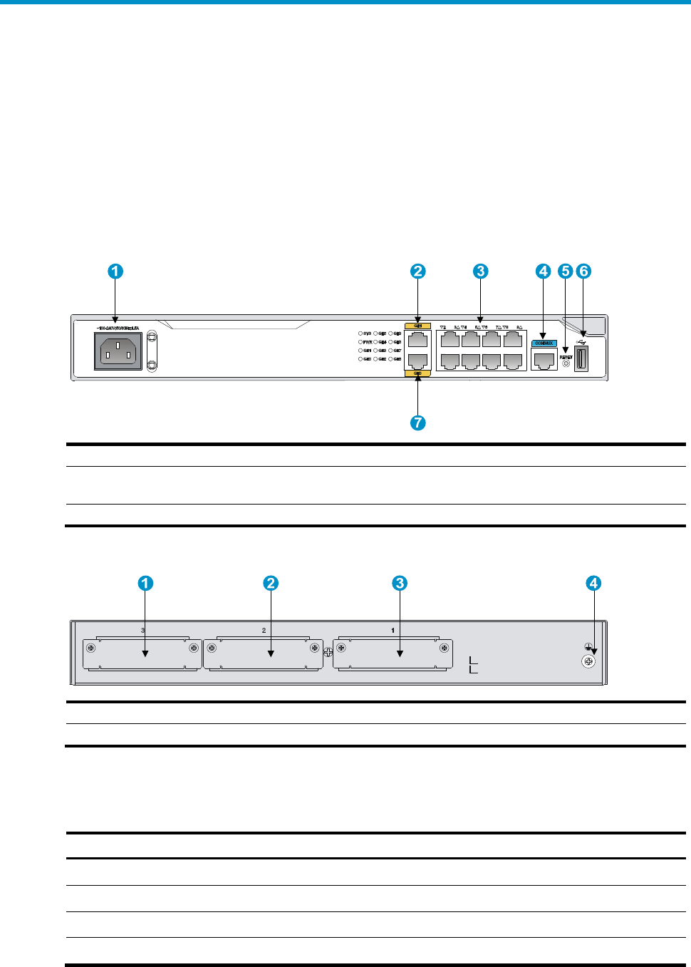
Figure 29 MSR1003-8 front view
(1) Power receptacle (2) Gi
g
abit Ethernet port (GE1)
(3) Gi
g
abit Ethernet port (GE2 to GE8)
(4) Console port/AUX port
(CON/AUX)
(5) Reset button (RESET) (6) USB port
(7) Gi
g
abit Ethernet port (GE0)
Figure 30 MSR1003-8 rear view
(1) SIC slot 3 (2) SIC slot 2
(3) SIC slot 1 (4) Groundin
g
terminal
Technical specifications
Item MSR1003-8
Console/AUX port 1
USB console port 1
USB port 1
Gigabit Ethernet port 10