
HP MSR1000 Router Series Installation Guide
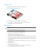
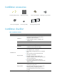
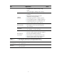
Table Of Contents
- Title Page
- Contents
- Preparing for installation
- Installing the router
- Replacement procedure
- Troubleshooting
- Appendix A Chassis views and technical specifications
- Appendix B LEDs
- Appendix C Slot arrangement
- Support and other resources
- Index
5
Installation accessories
Installation checklist
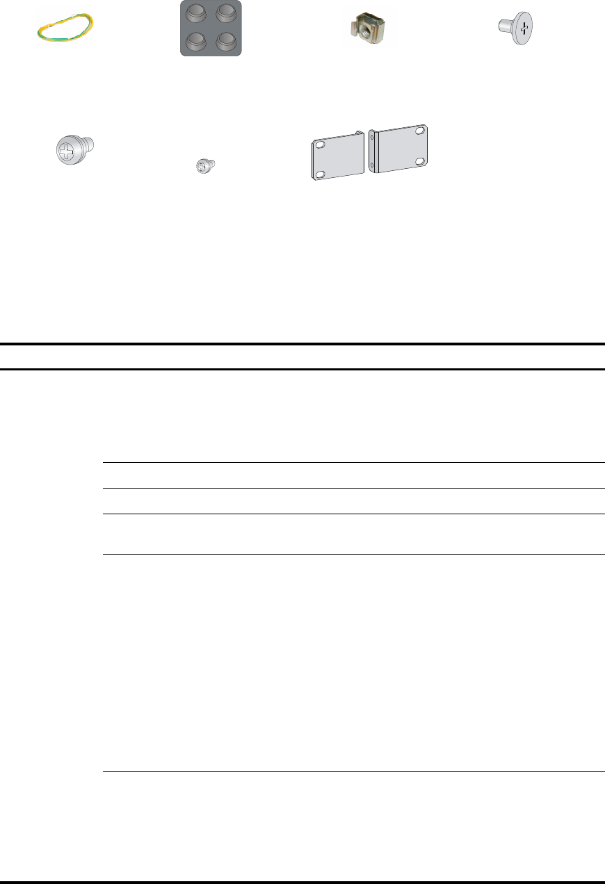
Table 5 Installation checklist
Item Re
q
uirements
Result
Installation site
Ventilation
• There is a minimum clearance of 10 cm (3.94 in)
around the inlet and outlet air vents for heat
dissipation of the router chassis.
• A good ventilation system is available at the
installation site.
Temperature 0°C to 45°C (32°F to 113°F).
Relative humidity 5% to 90% (noncondensing).
Cleanness
• Dust concentration ≤ 3 × 10
4
particles/m
3
. (No
visible dust on desk within three days.)
ESD prevention
• The equipment and floor are correctly grounded.
• The equipment room is dust-proof.
• The humidity and temperature are at a compliant
level.
• Wear an ESD wrist strap and uniform when
touching a circuit board.
• Place the removed interface module on an
antistatic workbench, with the face upward, or put
it into an antistatic bag.
• Touch only the edges, instead of electronic
components when observing or moving a removed
interface module.
EMI prevention
• Take effective measures to reduce interference
from the power grid system.
• Separate the grounding equipment of the router
from the grounding or lightning protection
grounding equipment of other devices as far as
possible.
Load-bearing screw (provided)
Cage nut (user supplied)
Grounding cable (provided)
Rubber feet (provided)
M6 screw (user supplied)
Mounting brackets (provided)M4 screw (provided)