HP MSR Router Series ACL and QoS Configuration Guide(V5) Part number: 5998-2027 Software version: CMW520-R2511 Document version: 6PW103-20140128
Legal and notice information © Copyright 2014 Hewlett-Packard Development Company, L.P. No part of this documentation may be reproduced or transmitted in any form or by any means without prior written consent of Hewlett-Packard Development Company, L.P. The information contained herein is subject to change without notice.
Contents Configuring ACLs ························································································································································· 1 Overview············································································································································································ 1 ACL categories ····································································································································
Configuring priority mapping ··································································································································· 28 Overview········································································································································································· 28 Introduction to priorities ········································································································································ 28
Defining a class ····················································································································································· 57 Defining a traffic behavior ··································································································································· 58 Defining a QoS policy ·········································································································································· 61 Applying the Qo
HTTP packet ··························································································································································· 86 RTP packet ······························································································································································ 86 RTCP packet ···························································································································································
Configuring FR fragmentation····································································································································· 115 Configuration restrictions and guidelines ········································································································· 115 Enabling FR fragmentation for an FR interface ································································································ 115 Enable FR fragmentation for FR PVCs ···········
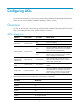
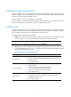
Configuring ACLs An access control list (ACL) is a set of rules (or permit or deny statements) for identifying traffic based on criteria such as source IP address, destination IP address, and port number. Overview You can use ACLs in QoS, firewall, routing, and other feature modules for identifying traffic. The packet drop or forwarding decisions varies with the modules that use ACLs.
Numbering and naming ACLs Each ACL category has a unique range of ACL numbers. When creating an ACL, you must assign it a number. In addition, you can assign the ACL a name for ease of identification. After creating an ACL with a name, you cannot rename it or delete its name. You cannot assign a name to a WLAN ACL or simple ACL. For an IPv4 basic or advanced ACLs, its ACL number and name must be unique in IPv4, and for an IPv6 basic or advanced ACL, its ACL number and name must be unique in IPv6.
ACL category Sequence of tie breakers 13. VPN instance 14. Protocol number IPv6 advanced ACL 15. Longer prefix for the source IPv6 address 16. Longer prefix for the destination IPv6 address 17. Narrower TCP/UDP service port number range 18. Rule configured earlier Ethernet frame header ACL 19. More 1s in the source MAC address mask (more 1s means a smaller MAC address) 20. More 1s in the destination MAC address mask 21.
For example, if the numbering step is 5 (the default), and there are five ACL rules numbered 0, 5, 9, 10, and 12, the newly defined rule is numbered 15. If the ACL does not include any rule, the first rule is numbered 0. Whenever the step changes, the rules are renumbered, starting from 0. For example, if there are five rules numbered 5, 10, 13, 15, and 20, changing the step from 5 to 2 causes the rules to be renumbered 0, 2, 4, 6, and 8.
1. Combining all periodic statements. 2. Combining all absolute statements. 3. Taking the intersection of the two statement sets as the active period of the time range. To configure a time range: Step 1. 2. Command Remarks Enter system view. system-view N/A By default, no time range exists. Configure a time range.
Step Command Remarks Optional. 6. Add or edit a rule comment. rule rule-id comment text 7. Add or edit a rule range remark. rule [ rule-id ] remark text By default, no rule comments are configured. Optional. By default, no rule range remarks are configured. Configuring a basic ACL Configuring an IPv4 basic ACL IPv4 basic ACLs match packets based only on source IP addresses. To configure an IPv4 basic ACL: Step 1. Enter system view. Command Remarks system-view N/A By default, no ACL exists.
To configure an IPv6 basic ACL: Step Command Remarks N/A 1. Enter system view. system-view 2. Create an IPv6 basic ACL view and enter its view. acl ipv6 number acl6-number [ name acl6-name ] [ match-order { auto | config } ] Configure a description for the IPv6 basic ACL. description text Set the rule numbering step. step step-value Create or edit a rule.
Step Command Remarks By default, no ACL exists. 2. 3. 4. 5. Create an IPv4 advanced ACL and enter its view. acl number acl-number [ name acl-name ] [ match-order { auto | config } ] Configure a description for the IPv4 advanced ACL. description text Set the rule numbering step. step step-value Create or edit a rule.
Step 1. Enter system view. Command Remarks system-view N/A By default, no ACL exists. 2. Create an IPv6 advanced ACL and enter its view. acl ipv6 number acl6-number [ name acl6-name ] [ match-order { auto | config } ] You can use the acl ipv6 name acl6-name command to enter the view of a named ACL. Optional. 3. Configure a description for the IPv6 advanced ACL. description text 4. Set the rule numbering step. step step-value Create or edit a rule.
Step Command Remarks By default, no ACL exists. Create an Ethernet frame header ACL and enter its view. acl number acl-number [ name acl-name ] [ match-order { auto | config } ] Configure a description for the Ethernet frame header ACL. description text Set the rule numbering step. step step-value 5. Create or edit a rule.
Step Command Remarks 4. Create or edit a rule. rule [ rule-id ] { deny | permit } [ { l2 rule-string rule-mask offset }&<1-8> ] [ counting | time-range time-range-name ] * By default, a user-defined ACL does not include any rule. 5. Add or edit a rule comment. rule rule-id comment text 6. Add or edit a rule range remark. Optional. By default, no rule comments are configured. Optional. rule [ rule-id ] remark text By default, no rule range remarks are configured.
Copying an ACL You can create an ACL by copying an existing ACL (source ACL). The new ACL (destination ACL) has the same properties and content (including the match order, rule numbering step, rules, ACL description, , and rule comment) as the source ACL, but not the same ACL number and name. To successfully copy an ACL, make sure that: • The destination ACL number is from the same category as the source ACL number. • The source ACL already exists, but the destination ACL does not.
Task Command Remarks Clear statistics for one or all WLAN, IPv4 basic, IPv4 advanced, Ethernet frame header, and user-defined ACLs. reset acl counter { acl-number | all | name acl-name } Available in user view. Clear statistics for one or all IPv6 basic and advanced ACLs. reset acl ipv6 counter { acl6-number | all | name acl6-name } Available in user view.
[DeviceA-acl-adv-3000] rule permit ip source 192.168.1.0 0.0.0.255 destination 192.168.0.100 0 [DeviceA-acl-adv-3000] rule permit ip source 192.168.2.0 0.0.0.255 destination 192.168.0.100 0 time-range work [DeviceA-acl-adv-3000] rule deny ip source any destination 192.168.0.100 0 [DeviceA-acl-adv-3000] quit # Enable IPv4 firewall, and apply IPv4 advanced ACL 3000 to filter outgoing packets on interface Ethernet 1/1.
ACL's step is 5 rule 0 permit ip source 192.168.1.0 0.0.0.255 destination 192.168.0.100 0 rule 5 permit ip source 192.168.2.0 0.0.0.255 destination 192.168.0.100 0 time-range work (4 times matched) (Active) rule 10 deny ip destination 192.168.0.100 0 (4 times matched) The output shows rule 5 is active. Rule 5 and rule 10 have been matched four times as the result of the ping operations. IPv6 advanced ACL configuration example Network requirements A company interconnects its departments through Device A.
[DeviceA-acl6-adv-3000] quit # Enable IPv6 firewall, and apply IPv6 advanced ACL 3000 to filter outgoing packets on interface Ethernet 1/1. [DeviceA] firewall ipv6 enable [DeviceA] interface ethernet 1/1 [DeviceA-Ethernet1/1] firewall packet-filter ipv6 3000 outbound [DeviceA-Ethernet1/1] quit Verifying the configuration # Ping the database server from a PC in the Financial department during working hours. (All PCs in this example use Windows XP.
The output shows rule 5 is active. Rule 5 and rule 10 have been matched four times as the result of the ping operations.
QoS overview In data communications, Quality of Service (QoS) is a network's ability to provide differentiated service guarantees for diversified traffic in terms of bandwidth, delay, jitter, and drop rate. Network resources are scarce. The contention for resources requires that QoS prioritize important traffic flows over trivial ones. For example, when bandwidth is fixed, more bandwidth for one traffic flow means less bandwidth for the other traffic flows.
QoS techniques overview The QoS techniques include traffic classification, traffic policing, traffic shaping, rate limit, congestion management, and congestion avoidance. The following section briefly introduces these QoS techniques.
perform traffic policing for incoming traffic, traffic shaping for outgoing traffic, congestion avoidance before congestion occurs, and congestion management when congestion occurs.
QoS configuration approaches QoS configuration approach overview You can configure QoS in the following approaches: • MQC approach • Non-MQC approach Some features support both approaches, but some support only one. MQC approach In the modular QoS configuration (MQC) approach, you configure QoS service parameters by using QoS policies. A QoS policy defines the shaping, policing, or other QoS actions to take on different classes of traffic. It is a set of class-behavior associations.
Figure 5 QoS policy configuration procedure Defining a class The system predefines some classes and defines general match criteria for them. A user-defined class cannot be named the same as a system-defined class. You can use these predefined classes when defining a policy. The system-defined classes include: The default class • default-class: Matches the default traffic. DSCP-based predefined classes • ef, af1, af2, af3, af4: Matches IP DSCP value ef, af1, af2, af3, af4, respectively.
Configure match criteria. 3. if-match [ not ] match-criteria For more information, see the if-match command in ACL and QoS Command Reference. Defining a traffic behavior A traffic behavior is a set of QoS actions (such as traffic filtering, shaping, policing, and priority marking) to take on a class of traffic. The system predefines some traffic behaviors and defines general QoS actions for them. A user-defined behavior cannot be named the same as a system-defined behavior.
Configuring QoS policy nesting You can reference a QoS policy in a traffic behavior to re-classify the traffic class associated with the behavior and take action on the re-classified traffic as defined in the policy. The QoS policy referenced in the traffic behavior is called the "child policy." The QoS policy that references the behavior is called the "parent policy." To nest QoS policies successfully, follow these guidelines: • The support for QoS policy nesting depends on your device model.
Control plane—The policy takes effect on the traffic sent or received on the control plane. • You can modify classes, behaviors, and class-behavior associations in an applied QoS policy unless it is applied to online users. If a class references an ACL for traffic classification, you can delete or modify the ACL (such as add rules to, delete rules from, and modify rules of the ACL).
Step Command Remarks Enter user profile view. user-profile profile-name The configuration made in user profile view takes effect when the user profile is activated and the users of the user profile are online. 3. Apply the QoS policy. qos apply policy policy-name { inbound | outbound } Use the inbound keyword to apply the QoS policy to the incoming traffic of the device (traffic sent by the online users).
Displaying and maintaining QoS policies Task Command Remarks Display traffic class configuration. display traffic classifier { system-defined | user-defined } [ classifier-name ] [ | { begin | exclude | include } regular-expression ] Available in any view. Display traffic behavior configuration. display traffic behavior { system-defined | user-defined } [ behavior-name ] [ | { begin | exclude | include } regular-expression ] Available in any view.
Configuring priority mapping Overview When a packet arrives, depending on your configuration, a device assigns a set of QoS priority parameters to the packet based on either a certain priority field carried in the packet or the port priority of the incoming port. This process is called "priority mapping." During this process, the device can modify the priority of the packet depending on device status. The set of QoS priority parameters decides the scheduling priority and forwarding priority of the packet.
In this approach, you can configure a port to look up a certain priority, 802.1p for example, in incoming packets, in the priority mapping tables. If no packet priority is trusted, the port priority of the incoming port is used. Changing port priority. • By default, all ports are assigned the port priority of zero. By changing the port priority of a port, you change the priority of the incoming packets on the port.
Configuring the trusted packet priority type for an interface or port group The following matrix shows the feature and router compatibility: Feature Configuring trusted packet priority type dscp MSR93 X MSR900 No Yes MSR20-1 X No MSR20 MSR30 MSR50 MSR1000 No Yes with only MSR30-11E and MSR30-11F routers No Yes When you configure the trusted packet priority type on an interface or port group, use the following available keywords: • dot1p—Uses the 802.
Step Command Remarks • Enter interface view: 2. Enter interface view or port group view. • Enter port group view: Settings in interface view (Ethernet or WLAN-ESS) take effect on the current interface. Settings in port group view take effect on all ports in the port group. qos priority priority-value The default setting is 0. interface interface-type interface-number port-group manual port-group-name 3. Set the port priority of the interface. Use one of the commands.
Figure 6 Network diagram Device A Internet Eth IP 1/1 pre ce de nc e3 Server Eth 1/1 1 ce /2 eden 1 h Et prec IP Eth1/3 1/2 Eth Device C Device B Configuration procedure 1. Configure Device C to trust port priority. # Assign port priority to Ethernet 1/1 and Ethernet 1/2. Make sure that the priority of Ethernet 1/1 is higher than Ethernet 1/2, and no trusted packet priority type is configured on Ethernet 1/1 or Ethernet 1/2.
Configuring traffic policing, traffic shaping, and rate limit Overview Traffic policing, traffic shaping, and rate limit are QoS techniques that help assign network resources, such as assign bandwidth. They increase network performance and user satisfaction. For example, you can configure a flow to use only the resources committed to it in a certain time range. This avoids network congestion caused by burst traffic.
• Peak information rate (PIR)—Rate at which tokens are put into bucket E, which specifies the average packet transmission or forwarding rate allowed by bucket E. • Excess burst size (EBS)—Size of bucket E, which specifies the transient burst of traffic that bucket E can forward. CBS is implemented with bucket C, and EBS with bucket E. In each evaluation, packets are measured against the following bucket scenarios: • If bucket C has enough tokens, packets are colored green.
Traffic shaping Traffic shaping supports shaping the inbound traffic and the outbound traffic. Traffic shaping limits the outbound traffic rate by buffering exceeding traffic. You can use traffic shaping to adapt the traffic output rate on a device to the input traffic rate of its connected device to avoid packet loss. The difference between traffic policing and GTS is that packets to be dropped with traffic policing are retained in a buffer or queue with GTS, as shown in Figure 8.
Rate limit also uses token buckets for traffic control. When rate limit is configured on an interface, are a token bucket handles all packets to be sent through the interface for rate limiting. If enough tokens are in the token bucket, packets can be forwarded. Otherwise, packets are put into QoS queues for congestion management. In this way, the traffic passing the physical interface is controlled.
Configuring traffic policing in policy approach Step Command 1. Enter system view. system-view 2. Create a class and enter class view. traffic classifier classifier-name [ operator { and | or } ] 3. Configure match criteria. if-match [ not ] match-criteria 4. Return to system view. quit 5. Create a behavior and enter behavior view. traffic behavior behavior-name 6. Configure a traffic policing action.
Configuring ACL-based traffic policing Step Command Remarks 1. Enter system view. system-view N/A 2. Configure an ACL. See "Configuring ACLs." Configure rules for the ACL. • Enter interface view: Use one of the commands. 3. Enter interface view or port group view. interface interface-type interface-number • Enter port group view: Settings in interface view take effect on the current interface. Settings in port group view take effect on all ports in the port group.
Step Command Create a behavior and enter behavior view. 5. traffic behavior behavior-name • In absolute value: gts cir committed-information-rate [ cbs committed-burst-size [ ebs excess-burst-size [ queue-length queue-length ] ] ] Configure a GTS action. 6. • In percentage: gts percent cir cir-percent [ cbs cbs-time [ ebs ebs-time ] ] 7. Return to system view. quit 8. Create a policy and enter policy view. qos policy policy-name 9.
Step 2. Enter interface view or port group view. Command Remarks • Enter interface view: Use one of the commands. • Enter port group view: Settings in interface view take effect on the current interface. Settings in port group view take effect on all ports in the port group. qos gts any cir committed-information-rate [ cbs committed-burst-size [ ebs excess-burst-size [ queue-length queue-length ] ] ] N/A interface interface-type interface-number port-group manual port-group-name 3.
Traffic policing and GTS configuration examples Traffic policing and GTS configuration example Network requirements As shown in Figure 11: • Server, Host A, and Host B can access the Internet through Router A and Router B. • Server, Host A, and Ethernet 1/1 of Router A are in the same network segment. • Host B and Ethernet 1/2 of Router A are in the same network segment.
[RouterA-acl-basic-2001] quit [RouterA] acl number 2002 [RouterA-acl-basic-2002] rule permit source 1.1.1.2 0 [RouterA-acl-basic-2002] quit # Configure CAR policies for different flows received on Ethernet 1/1. [RouterA] interface ethernet 1/1 [RouterA-Ethernet1/1] qos car inbound acl 2001 cir 54 cbs 4000 ebs 0 green pass red remark-prec-pass 0 [RouterA-Ethernet1/1] qos car inbound acl 2002 cir 8 cbs 1875 ebs 0 green pass red discard [RouterA-Ethernet1/1] quit 2.
system-view [Router] qos carl 1 source-ip-address range 2.1.1.1 to 2.1.1.
Configuring congestion management Overview Causes, impacts, and countermeasures of congestion Congestion occurs on a link or node when traffic size exceeds the processing capability of the link or node. It is typical of a statistical multiplexing network and can be caused by link failures, insufficient resources, and various other causes. Figure 13 shows some common congestion scenarios.
FIFO Figure 14 FIFO queuing As shown in Figure 14, the first in first out (FIFO) uses a single queue and does not classify traffic or schedule queues. FIFO delivers packets depending on their arrival order, with the one arriving earlier scheduled first. The only concern of FIFO is queue length, which affects delay and packet loss rate. On a device, resources are assigned for packets depending on their arrival order and load status of the device. The best-effort service model uses FIFO queuing.
Priority queuing schedules the four queues in the descending order of priority. It sends packets in the queue with the highest priority first. When the queue with the highest priority is empty, it sends packets in the queue with the second highest priority. In this way, you can assign the mission-critical packets to the high priority queue to make sure that they are always served first.
Weighted fair queuing Figure 17 Weighted fair queuing (WFQ) Before WFQ is introduced, make sure that you have understood fair queuing (FQ). FQ is designed for fairly allocating network resources to reduce delay and jitter of each traffic flow as possible. In an attempt to balance the interests of all parties, FQ follows these principles: • Different queues have fair dispatching opportunities for delay balancing among streams.
CBQ Figure 18 CBQ Class-based queuing (CBQ) extends WFQ by supporting user-defined classes. When network congestion occurs, CBQ uses user-defined traffic match criteria to enqueue packets. Before that, congestion avoidance actions, such as tail drop or WRED and bandwidth restriction check, are performed before packets are enqueued. When being dequeued, packets are scheduled by WFQ. CBQ provides the following queues: • Emergency queue—Enqueues emergent packets.
• Match packets with priority classes in the configuration order. • Match packets with other classes in the configuration order. • Match packets with classification rules in a class in the configuration order. RTP priority queuing Real-time transport protocol (RTP) priority queuing is a simple queuing technique designed to guarantee QoS for real-time services (including voice and video services).
Table 3 Congestion management technique comparison Type Number of queues Advantages Disadvantages • All packets are treated equally. The available bandwidth, delay and drop probability are determined by the arrival order of packets. • No need to configure, easy FIFO 1 to use. • Easy to operate, low delay.
Type Number of queues Advantages Disadvantages • Flexible traffic classification based on various rules and differentiated queue scheduling mechanisms for EF, AF and BE services. • Highly precise bandwidth guarantee and queue scheduling on the basis of AF service weights for various AF services. CBQ Configurable (0 to 64) • Absolutely preferential queue scheduling for the EF service to meet the delay requirement of real-time data. The system overheads are large.
PPPoA, PPPoEoA, PPPoFR, or MPoFR (frame relay traffic shaping is not enabled on the frame relay interface). Configuration example # Set the FIFO queue size to 100. system-view [Sysname] interface ethernet1/1 [Sysname-Ethernet1/1] qos fifo queue-length 100 Configuring PQ You can define multiple rules for a priority queue list (PQL) and apply the list to an interface or PVC. When a packet arrives at the interface or PVC, the system matches the packet with each rule in the order configured.
• Enter interface view: 5. Enter interface view or PVC view. interface interface-type interface-number • Enter PVC view: N/A a. interface atm interface-number b. pvc vpi/vci 6. Apply the PQ list to the interface. qos pq pql pql-index 7. Display PQ list configuration information.
[RouterA] acl number 2002 [RouterA-acl-basic-2002] rule permit source 1.1.1.2 0.0.0.0 # Configure a PQ list that assigns the packets from Server to the top queue and those from Host A to the bottom queue when congestion occurs. Set the maximum queue size of the top queue to 50 and that of the bottom queue to 100 in the PQ list.
5. Configure the bytes sent from a queue during a cycle of round robin queue scheduling. qos cql cql-index queue queue-number serving byte-count Optional. • Enter interface view: 6. Enter interface view or PVC view. interface interface-type interface-number • Enter PVC view: N/A a. interface atm interface-number b. pvc vpi/vci 7. 8. 9. Apply the CQ list to the interface or PVC. qos cq cql cql-index Display interface/PVC CQ list configuration information.
Configuration procedure On an interface or PVC without WFQ configured, the qos wfq command can enable WFQ and configure WFQ-related parameters. If WFQ is configured for the interface or PVC, the qos wfq command can modify the WFQ-related parameters. To configure WFQ: Step 1. Enter system view. Command Remarks system-view N/A • Enter interface view: 2. Enter interface view or PVC view. interface interface-type interface-number • Enter PVC view: N/A a. interface atm interface-number b.
Predefined classes, traffic behaviors, and policies The system predefines the following classes, traffic behaviors, and policies: Predefined classes The system predefines some classes and defines general rules for them. You can use these predefined classes when defining a policy. The default class • default-class—Matches the default traffic. DSCP-based predefined classes • ef, af1, af2, af3, af4—Matches IP DSCP value ef, af1, af2, af3, af4, respectively.
Configure match criteria. 3. if-match [ not ] match-criteria N/A Defining a traffic behavior To define a traffic behavior, create the traffic behavior first and then configure QoS attributes in traffic behavior view. Configure AF and the minimum guaranteed bandwidth When you configure AF and the minimum guaranteed bandwidth, follow these guidelines: • You can apply this traffic behavior only to the outgoing traffic of an interface or ATM PVC.
Configuring WFQ To configure WFQ: Step Command Remarks 1. Enter system view. system-view N/A 2. Create a traffic behavior and enter traffic behavior view. traffic behavior behavior-name The specified traffic behavior name cannot be the name of any system-defined behavior. 3. Configure WFQ. queue wfq [ queue-number total-queue-number ] N/A You can associate the traffic behavior that contains a WFQ action only with the default class.
• dscp—Uses the DSCP value for calculating the drop probability for a packet. 3. Use WRED drop. wred [ dscp | ip-precedence ] • ip-precedence—Uses the IP precedence value for calculating the drop probability for a packet. This keyword is used by default.
Configuring the lower limit, upper limit, and drop probability denominator for each IP precedence value in WRED To perform this configuration, make sure IP precedence-based WRED has been enabled with the wred ip-precedence command. Disabling WRED also removes the wred ip-precedence command configuration Removing the queue af or queue wfq command configuration also removes the WRED drop-related parameters.
• An inbound QoS policy cannot contain a GTS action or any of these queuing actions: queue ef, queue af, or queue wfq. • You must enable the rate limit function for the queuing function to take effect on these interfaces: tunnel interfaces, subinterfaces, HDLC link bundle interfaces, and VT/dialer interfaces configured with PPPoE, PPPoA, PPPoEoA, PPPoFR, or MPoFR (frame relay traffic shaping is not enabled on the frame relay interface).
max-bandwidth command configured, if the sum of sub-channel bandwidth equals to or exceeds the sum of AF bandwidth and EF bandwidth, AF and EF calculate bandwidth based on the actual interface bandwidth. Otherwise, AF and EF calculate bandwidth based on 1 Gbps of bandwidth, and the message indicating insufficient bandwidth is displayed. In the latter case, the queuing function might fail to take effect.
• Enter interface view: Enter interface view or PVC view. 2. interface interface-type interface-number • Enter PVC view: N/A a. interface atm interface-number b. pvc vpi/vci Set the maximum reserved bandwidth as a percentage of available bandwidth. 3. qos reserved-bandwidth pct percent The default setting is 80. Displaying and maintaining CBQ Task Command Remarks Display class configuration information.
Figure 21 Network diagram Configuration procedure Configure Router A: # Define three classes to match the IP packets with the DSCP values AF11, AF21, and EF, respectively.
# Apply the QoS policy to the outgoing traffic of ATM PVC ATM 1/0. [RouterA] interface atm 1/0 [RouterA-atm1/0] ip address 1.1.1.1 255.255.255.0 [RouterA-atm1/0] pvc qostest 0/40 [RouterA-atm-pvc-atm1/0-0/40-qostest] qos apply policy dscp outbound The configuration enables EF traffic to be forwarded preferentially when congestion occurs. Configuring RTP priority queuing Configuration procedure To configure RTP priority queuing: Step 1. 2. Enter system view. Enter interface view or PVC view.
# Configure RTP priority queuing on interface Serial 2/0: the start port number is 16384, the end port number is 32767, and 64 kbps of bandwidth is reserved for RTP packets. When congestion occurs to the outgoing interface, RTP packets are assigned to the RTP priority queue. [Sysname-Serial2/0] qos rtpq start-port 16384 end-port 32767 bandwidth 64 Configuring QoS tokens Because the upper layer protocol TCP provides traffic control, CQ and WFQ might become invalid during FTP transmission.
Configuring packet information pre-extraction If a tunnel interface has processed an incoming IP packet, for example, if the tunnel interface has used GRE to encapsulate a packet, the GRE-encapsulated packet enters the QoS module for processing. As a result, the QoS module cannot get the IP information of the original packets. To process the original IP packets with QoS on the physical interface for a logical interface, configure packet information pre-extraction on the logical interface.
Configuration procedure To configure local fragment pre-drop: Step Command Remarks 1. Enter system view. system-view N/A 2. Enter interface view. interface interface-type interface-number N/A 3. Enable local fragment pre-drop. qos fragment pre-drop By default, local fragment pre-drop is disabled. Configuration example Network requirements Enable local fragment pre-drop on an interface. Configuration procedure # Enable local fragment pre-drop on interface Serial 2/0.
Configuring congestion avoidance Overview Avoiding congestion before it occurs is a proactive approach to improving network performance. As a flow control mechanism, congestion avoidance actively monitors network resources (such as queues and memory buffers), and drops packets when congestion is expected to occur or deteriorate. Compared with end-to-end flow control, this flow control mechanism controls the load of more flows in a device.
With WFQ queuing used, you can set the exponent for average queue size calculation, upper threshold, lower threshold, and drop probability for packets with different precedence values to provide differentiated drop policies. With FIFO queuing, PQ, or CQ used, you can set the exponent for average queue size calculation, upper threshold, lower threshold, and drop probability for each queue to provide differentiated drop policies for different classes of packets.
Denominator for drop probability calculation—The bigger the denominator is, the smaller the calculated drop probability is. • Configuring WRED on an interface Configuration procedure CAUTION: To configure the qos wred enable command on an interface, make sure that WFQ queuing has been applied on the interface. To configure WRED on an interface: Step 1. Enter system view. Command Remarks system-view N/A • Enter interface view: 2. Enter interface view or PVC view.
# Set the following parameters for packets with IP precedence 3: lower threshold 20, upper threshold 40, and drop probability denominator 15. [Sysname-Ethernet1/1] qos wred ip-precedence 3 low-limit 20 high-limit 40 discard-probability 15 # Set the exponential factor for the average queue size calculation to 6.
Apply the WRED table to the interface or port group. 5. qos wred apply table-name A queue-based WRED table is available on only Layer 2 ports. Configuration example Apply a queue-based WRED table to Layer 2 port Ethernet 1/1: # Enter system view. system-view # Configure a queue-based WRED table. [Sysname] qos wred queue table queue-table1 [Sysname-wred-table-queue-table1] quit # Enter interface view. [Sysname] interface ethernet 1/1 # Apply the queue-based WRED table to Ethernet 1/1.
Figure 23 Network diagram Configuration procedure # Configure ACLs to match the packets from Server, Telephone, Host A, and Host B, respectively. system-view [Router] acl number 2001 [Router-acl-basic-2001] rule 1 permit source 10.1.1.1 0 [Router-acl-basic-2001] quit [Router] acl number 2002 [Router-acl-basic-2002] rule 2 permit source 10.1.1.2 0 [Router-acl-basic-2002] quit [Router] acl number 2003 [Router-acl-basic-2003] rule 3 permit source 10.1.1.
[Router] traffic behavior behavior3 [Router-behavior-behavior3] remark ip-precedence 3 [Router-behavior-behavior3] quit [Router] traffic behavior behavior4 [Router-behavior-behavior4] remark ip-precedence 2 [Router-behavior-behavior4] quit [Router] qos policy aa [Router-qospolicy-aa] classifier class1 behavior behavior1 [Router-qospolicy-aa] classifier class2 behavior behavior2 [Router-qospolicy-aa] classifier class3 behavior behavior3 [Router-qospolicy-aa] classifier class4 behavior behavior4 [Router-qospo
Configuring traffic filtering You can filter in or filter out a class of traffic by associating the class with a traffic filtering action. For example, you can filter packets sourced from a specific IP address according to network status. Configuration procedure To configure traffic filtering: Step Command Remarks 1. Enter system view. system-view N/A 2. Create a class and enter class view. traffic classifier classifier-name [ operator { and | or } ] N/A 3. Configure match criteria.
Traffic filtering configuration example Network requirements As shown in Figure 24, configure traffic filtering to filter the packets with source port not being 21, and received on Ethernet 1/1. Figure 24 Network diagram Configuration procedure # Create advanced ACL 3000, and configure a rule to match packets whose source port number is not 21.
Configuring priority marking Priority marking sets the priority fields or flag bits of packets to modify the priority of traffic. For example, you can use priority marking to set IP precedence or DSCP for a class of IP traffic to change its transmission priority in the network. To configure priority marking, you can associate a class with a behavior configured with the priority marking action to set the priority fields or flag bits of the class of packets.
Step Command Remarks 15. Display the priority marking configuration. display traffic behavior { system-defined | user-defined } [ behavior-name ] [ | { begin | exclude | include } regular-expression ] Optional. 80 Available in any view.
Configuring traffic redirecting Feature and hardware compatibility Feature Traffic redirecting MSR90 0 No MSR93 X No MSR20-1 X No MSR20 MSR30 MSR50 MSR1000 Yes (only redirecting traffic to the CPU) Yes with only MSR30-11E and MSR30-11F routers and MIM Layer 2 Ethernet switching modules Yes with only FIC Layer 2 Ethernet switching modules Yes Overview Traffic redirecting is the action of redirecting the packets matching the specific match criteria to a certain location for processing.
Step Command Remarks 4. Return to system view. quit N/A 5. Create a behavior and enter behavior view. traffic behavior behavior-name N/A 6. Configure a traffic redirecting action. redirect { cpu | interface interface-type interface-number } Optional. 7. Return to system view. quit N/A 8. Create a policy and enter policy view. qos policy policy-name N/A 9. Associate the class with the traffic behavior in the QoS policy.
Configuring DAR Overview The Deeper Application Recognition (DAR) feature identifies packets of dynamic protocols like BitTorrent, HTTP, FTP, and RTP by examining Layer 4 to Layer 7 content other than the IP header. The feature helps service providers and businesses limit aggressive bandwidth use by applications like BitTorrent to ensure fairness and network performance. BitTorrent is a P2P file sharing communications protocol, which enables personal computers to directly exchange data or services.
Protocol field value Protocol 4 IPinIP 6 TCP 8 EGP 17 UDP 47 GRE 50 ESP 51 AH 88 EIGRP Flags field for fragmentation in the IP header Figure 26 shows the format of the 3-bit flags in an IP packet. Figure 26 Format of the 3-bit flags The lower 2 bits of the flags field control IP packet fragmentation. The 3 bits in the flags field are defined as follows: • Reserved—Must be 0. • Do not fragment—0 indicates fragmentation is allowed, and 1 indicates fragmentation is forbidden.
TCP packet TCP packet format Figure 27 TCP packet format 3 0 9 15 31 Source port number Destination port number Sequence number Acknowledgement number HLEN Reserved U A P R S F R C S S Y I G K H T N N Window size TCP checksum Urgent pointer Option (if any) Data (if any) Table 5 Description on the 6 flag bits in the TCP header Flag bit Description URG The urgent pointer is valid. ACK The acknowledgement number is valid.
UDP packet Figure 29 UDP packet format 0 15 31 Source port number Destination port number UDP length UDP checksum Data (if any) Like TCP, protocols using UDP can be static or dynamic. Static protocols use fixed port numbers for interaction and dynamic protocols use negotiated port numbers. HTTP packet HTTP packets include request packets and response packets. Figure 30 HTTP packet format • The header of an HTTP request packet consists of a request line and header.
Figure 31 RTP packet format 0 2 3 V 15 8 P X CC M 31 PT Sequence Number Time Stamp SSRC CSRC identifiers …… Payload The fields are described as follows: • V—2 bits, version number. • P—1 bit, padding flag. • X—1 bit, packet header extension flag. • CC—4 bits, contributor count. • M—1 bit, special event flag. • PT—7 bits, payload type flag. • Sequence Number—16 bits, data packet sequence number. • Time Stamp—32 bits, time stamp. • SSRC—32 bits, synchronization source identifier.
Figure 33 Header format of an SR-type RTCP packet The fields are described as follows: • V—2 bits, version number. • P—1 bits, padding flag. • RC—5 bits, the number of receiving report blocks in the RTCP packet. • PT—8 bits, RTCP packet type flag. This field is 200 for SR-type RTCP packets. • Length—16 bits, length of the RTCP packet. • SSRC of Sender—32 bits, SSRC of the sender.
Protocol name Protocol type Default port numbers LDAP TCP/UDP 389 Mgcp TCP 2427, 2428, 2727 Mgcp UDP 2427, 2727 Napster TCP 6699, 8875, 8888, 7777, 6700, 6666, 6677, 6688, 4444, 5555 NetBIOS TCP 137, 138, 139 NetBIOS UDP 137, 138, 139 Netshow TCP 1755 NFS TCP/UDP 2049 NNTP TCP/UDP 119 Notes TCP/UDP 1352 Novadign TCP/UDP 3460, 3461, 3462, 3463, 3464, 3465 NTP TCP/UDP 123 PCAnywhere TCP 5631, 65301 PCAnywhere UDP 22, 5632 POP3 TCP/UDP 110 Pptp TCP 1723 Printe
Protocol name Protocol type Default port numbers Sqlserver TCP 1433 SSH TCP 22 Streamwork UDP 1558 Sunrpc TCP/UDP 111 Syslog UDP 514 Telnet TCP 23 Tftp UDP 69 Vdolive TCP 7000 Winmx TCP 6699 X Windows TCP 6000, 6001, 6002, 6003 Configuring DAR for P2P traffic recognition DAR uses a .mtd P2P signature file for P2P traffic identification. It compares the content of every incoming packet with the signature file. If a match is found, DAR processes the packet as a P2P packet.
Step 3. Assign a protocol to the protocol group. Command Remarks protocol protocol-name By default, a protocol group contains no protocol. Enabling DAR for traffic recognition P2P traffic recognition is system resource demanding. It is disabled by default to avoid impacts on other modules. To enable DAR for traffic recognition: Step Command Remarks 1. Enter system view. system-view N/A 2. Enter interface view. interface interface-type interface-number N/A 3.
Step Command Remarks Optional. 3. Configure a match criterion for HTTP. if-match [ not ] protocol http [ url url-string | host hostname-string | mime mime-type ] DAR can classify HTTP packets by the URL address, host name, or MIME type in HTTP packets. By default, no match criterion is configured for HTTP. Optional. 4. 5. Configure a match criterion for RTP. if-match [ not ] protocol rtp [ payload-type { audio | video | payload-string&<1-16> } * ] Configure the match criterion for a protocol.
Renaming user-defined protocols By default, the names of the ten user-defined protocols are user-defined01, user-defined02,…, user-defined10. You can rename them following these steps to assist memorization and management. To rename user-defined protocols: Step Command 1. Enter system view. system-view 2. Rename a user-defined protocol.
Displaying and maintaining DAR for other types of traffic than P2P Task Command Remarks Display information about the DAR module. display dar information [ | { begin | exclude | include } regular-expression ] Available in any view. Display DAR protocol information. display dar protocol { protocol-name | all } [ | { begin | exclude | include } regular-expression ] Available in any view. Display information about renamed user-defined protocols.
[Router-behavior-deny] quit # Configure a QoS policy to match and filter FTP packets. [Router] qos policy ftppolicy [Router-qospolicy-ftppolicy] classifier ftpclass behavior deny [Router-qospolicy-ftppolicy] quit # Enable DAR for traffic recognition, and apply the QoS policy to the incoming traffic of Ethernet 1/1. [Router] interface ethernet 1/1 [Router-Ethernet1/1] dar enable [Router-Ethernet1/1] qos apply policy ftppolicy inbound Run FTP client software on a PC.
Because HTTP URL match criteria are for matching request packets, make sure that you are applying the QoS policy to the direction where HTTP URL request packets are present. HTTP host-based DAR configuration example Network requirements As shown in Figure 36, configure the router to prohibit Client from accessing the webpage http://www.abcd.com:8080/news/index.html on the Web server. Figure 36 Network diagram Configuration procedure # Configure the HTTP Host as the match criterion.
Appendixes Appendix A Acronyms Table 7 Acronyms Acronym Full spelling AF Assured Forwarding BE Best Effort BQ Bandwidth Queuing CAR Committed Access Rate CBS Committed Burst Size CBQ Class Based Queuing CBWFQ Class Based Weighted Fair Queuing CE Customer Edge CIR Committed Information Rate CQ Custom Queuing DAR Deeper Application Recognition DCBX Data Center Bridging Exchange Protocol DiffServ Differentiated Service DoS Denial of Service DSCP Differentiated Services Code Point
Acronym Full spelling PE Provider Edge PHB Per-hop Behavior PQ Priority Queuing QoS Quality of Service RED Random Early Detection RSVP Resource Reservation Protocol RTP Real-Time Transport Protocol SLA Service Level Agreement SP Strict Priority TE Traffic Engineering ToS Type of Service TP Traffic Policing TS Traffic Shaping VoIP Voice over IP VPN Virtual Private Network WFQ Weighted Fair Queuing WRED Weighted Random Early Detection WRR Weighted Round Robin Appendix B D
Input priority value dot1p-lp mapping 5 5 6 6 7 7 Table 9 Default dscp-lp priority mapping table Input priority value dscp-lp mapping DSCP Local precedence (lp) 0 to 7 0 8 to 15 1 16 to 23 2 24 to 31 3 32 to 39 4 40 to 47 5 48 to 55 6 56 to 63 7 Table 10 Default lp-dot1p priority mapping table Input priority value lp-dot1p mapping Local precedence (lp) 802.
Port priority Local precedence (lp) 6 6 7 7 Appendix C Introduction to packet precedences IP precedence and DSCP values Figure 37 ToS and DS fields As shown in Figure 37, the ToS field in the IPv4 header contains 8 bits, where the first 3 bits (0 to 2) represent IP precedence from 0 to 7. The Traffic Classes field in the IPv6 header contains 8 bits, where the first 3 bits (0 to 2) represent IP precedence from 0 to 7.
DSCP value (decimal) DSCP value (binary) Description 12 001100 af12 14 001110 af13 18 010010 af21 20 010100 af22 22 010110 af23 26 011010 af31 28 011100 af32 30 011110 af33 34 100010 af41 36 100100 af42 38 100110 af43 8 001000 cs1 16 010000 cs2 24 011000 cs3 32 100000 cs4 40 101000 cs5 48 110000 cs6 56 111000 cs7 0 000000 be (default) 802.1p priority 802.
Figure 39 802.1Q tag header Table 14 Description on 802.1p priority 802.1p priority (decimal) 802.1p priority (binary) Description 0 000 best-effort 1 001 background 2 010 spare 3 011 excellent-effort 4 100 controlled-load 5 101 video 6 110 voice 7 111 network-management 802.11e priority To provide QoS services on WLAN, the 802.11e standard was developed. IEEE 802.11e is a MAC-layer enhancement to IEEE 802.11. IEEE 802.11e adds a 2-byte QoS Control field to the 802.
As shown in Figure 41, the EXP field is 3 bits long and is in the range of 0 to 7.
Configuring FR QoS Overview On a FR interface, you can use generic QoS services to perform traffic policing, traffic shaping, congestion management, and congestion avoidance. You can also use FR-specific QoS mechanisms, including FR traffic shaping, FR traffic policing, FR congestion management, FR discard eligibility (DE) rule list, and FR queuing management. FR QoS is more flexible than generic QoS. It works on a per PVC basis, and generic QoS works on a per interface basis.
is present. Even if congestion occurs in the network, Router B can still transmit packets at the rate of 32 kbps. Figure 43 FRTS implementation FRTS uses the parameters CIR ALLOW, CIR, CBS, and EBS for traffic shaping. FR PVCs can transmit packets at the rate of CIR ALLOW. In case of bursty packets, FRTS allows an FR PVC to transmit packets at a rate exceeding CIR ALLOW. How FRTS works FRTS is implemented using token buckets.
Take sending an 800-byte packet for example. Given the CIR ALLOW of 64000 kbps, it takes Tc=6400/64000=0.1s (100ms) to put the required tokens into the token bucket. The packet is transmitted successfully after 6400 bits of tokens are put into the token bucket within 100 ms. FR traffic policing FR traffic policing monitors the traffic entering the network from each PVC and restricts the traffic within a permitted range.
• FIFO • PQ • CQ • WFQ • CBQ • RTPQ • PVC PQ Of these queuing mechanisms, FIFO, PQ, CQ, WFQ, CBQ, and RTPQ are universal queuing mechanisms. For more information, see "Configuring congestion management." PVC PQ can only be applied on FR interfaces. PVC priority queues include the following types: top, middle, normal, and bottom, in the descending priority order.
FR WRED In the current FR QoS implementation, only WRED queues, and AF and BE queues in CBWFQ support WRED, and EF queues in CBWFQ do not support WRED. For more information about WRED, see "Configuring congestion avoidance." FR QoS configuration task list Task Remarks Creating and configuring an FR class Required. Configuring FRTS Optional. Configuring FR traffic policing Optional. Configuring FR congestion management Optional. Configuring FR DE rule list Optional.
Step Command (Method 2) Map the FR class to an DLCI. Remarks c. Enter FR interface view: interface interface-type interface-number d. Enter FR PVC view: fr dlci dlci-number e. Map the FR class to the DLCI: fr-class class-name In FR class view, you can configure QoS parameters for QoS services such as FRTS, FR traffic policing, FR congestion management, and FR queuing. For more information about the parameter configurations, see the subsequent sections.
Step Command Set CIR for FR PVCs. 9. cir committed-information-rate Remarks Optional. The default setting is 56000 bps. Optional. 10. Enable FRTS adaptation. traffic-shaping adaptation { becn percentage | interface-congestion number } By default, the command is enabled with the percentage argument being 25 for traffic with the BECN flag.
Configuring FR congestion management for an FR interface The device determines whether congestion occurs based on the percentage of the current FR interface queue length to the total interface queue length. If the percentage exceeds the set congestion threshold, the device considers congestion has occurred and takes action on packets (for example, drops packets), to alleviate the condition. To configure FR congestion management for an FR interface: Step Command Remarks 1. Enter system view.
Step Command Remarks • Configure an interface-based DE rule list: fr del list-number inbound-interface interface-type interface-number 2. Configure a DE rule list. • Configure an IP-based DE rule list: 3. Enter FR interface view. interface interface-type interface-number fr del list-number protocol ip [ acl acl-number | fragments | greater-than bytes | less-than bytes | tcp ports | udp ports ] Use one of the commands. By default, no DE rule list is created.
Configuring CBQ on an FR PVC Step Command Remarks 8. Enter system view. system-view N/A 9. Create a class and enter class view. traffic classifier classifier-name [ operator { and | or } ] N/A 10. Configure the match criteria. if-match [ not ] match-criteria N/A 11. Return to system view. quit N/A 12. Create a behavior and enter behavior view. traffic behavior behavior-name N/A Configure AF and configure the minimum guaranteed bandwidth.
Step Command Remarks wred ip-precedence precedence low-limit low-limit high-limit high-limit [ discard-probability discard-prob ] Optional. 14. Return to system view. quit N/A 15. Create a policy and enter policy view. qos policy policy-name N/A 16. Associate the class with the traffic behavior in the QoS policy. classifier classifier-name behavior behavior-name N/A 17. Return to system view. quit N/A 18. Enter FR class view. fr class class-name N/A 19.
Configuring FR fragmentation The devices support end-to-end FRF.12 fragmentation. On low-speed FR links, large data packets cause excessive delay. FR fragmentation can fragment large FR packets into several small packets that can be transmitted on low-speed links with low delay. When voice packets and data packets are transmitted simultaneously, large data packets occupy the bandwidth for a long time. As a result, voice packets are delayed or even dropped, thus affecting voice quality.
Displaying and maintaining FR QoS Task Command Remarks Display the mapping relationship between FR classes and interfaces (including the DLCIs of an interface, subinterfaces of an interface, and the DLCIs of subinterfaces). display fr class-map { fr-class class-name | interface interface-type interface-number } [ | { begin | exclude | include } regular-expression ] Available in any view. Display the configuration and statistics information about FR QoS.
Configuration procedure # Define ACL 2001 and PQL 1 to assign IP packets sourced from the 10.0.0.0 network segment to the top queue. system-view [Router] acl number 2001 [Router-acl-basic-2001] rule permit source 10.0.0.0 0.255.255.255 [Router-acl-basic-2001] quit [Router] qos pql 1 protocol ip acl 2001 queue top # Create FR class 96k and configure its FRTS parameters.
# Enable FR encapsulation and FRTS on interface Serial 2/0. [RouterA] interface serial 2/0 [RouterA-Serial2/0] link-protocol fr [RouterA-Serial2/0] ip address 10.1.1.2 255.0.0.0 [RouterA-Serial2/0] fr traffic-shaping # Create DLCI 16, and apply the FR class test1 to DLCI 16. [RouterA-Serial2/0] fr dlci 16 [RouterA-fr-dlci-Serial2/0-16] fr-class test1 2. Configure Router B: # Create FR class test1, enable FR fragmentation, and set the fragment size to 128 bytes.
[RouterA-behavior-wfqwred] wred dscp af11 low-limit 5 high-limit 10 discard-probability 6 [RouterA-behavior-wfqwred] wred dscp af21 low-limit 10 high-limit 20 discard-probability 8 [RouterA-behavior-wfqwred] quit # Create QoS policy test and associate traffic behavior wfqwred with the default class default-class in the QoS policy.
# Create QoS policy test, and associate the default class default-class with behavior wfqwred and class af11_31 with behavior afwred in the QoS policy. [RouterB] qos policy test [RouterB-qospolicy-test] classifier default-class behavior wfqwred [RouterB-qospolicy-test] classifier af11_31 behavior afwred [RouterB-qospolicy-test] quit # Create FR class frclass and apply QoS policy test to the class.
Configuring MPLS QoS The MPLS-related knowledge is necessary for understanding MPLS QoS. For more information about MPLS, see MPLS Configuration Guide. For more information about EXP precedence, see "Configuring priority mapping." For more information about traffic policing, see "Configuring traffic policing, traffic shaping, and line rate." For more information about priority marking, see "Configuring priority marking.
Configuration prerequisites Complete basic MPLS configurations. For more information about basic MPLS configurations, see MPLS Configuration Guide. Configuration procedure To configure MPLS CAR: Step 1. Enter system view. Command Remarks system-view N/A • Enter interface view: 2. Enter interface view or port group view. • Enter port group view: Settings in interface view take effect on the current interface. Settings in port group view take effect on all ports in the port group.
Step Command Remarks Create a traffic behavior and enter traffic behavior view. traffic behavior behavior-name N/A Configure an EXP re-marking action in the behavior. remark mpls-exp exp-value N/A 7. Return to system view. quit N/A 8. Create a QoS policy and enter QoS policy view. qos policy policy-name N/A Associate the traffic class with the traffic behavior in the QoS policy.
Step Command Apply the PQ list to the interface. 4. qos pq pql pql-index Configure MPLS CQ Step Command 1. Enter system view. system-view 2. Configure an EXP-based CQ list. qos cql cql-index protocol mpls exp exp-value-list queue queue-number 3. Enter interface view. interface interface-type interface-number 4. Apply the CQ list to the interface. qos cq cql cql-index MPLS QoS configuration example Network requirements As shown in Figure 51: • Both CE 1 and CE 2 belong to VPN 1.
Figure 51 Network diagram P S2/1 S2/2 2M 2M PE 1 PE 2 S2/1 Loop0 S2/2 Loop0 AS 100 Eth1/1 Eth1/2 100M 100M Eth1/2 Eth1/3 CE 1 VPN 1 AS 65410 CE 2 VPN 1 AS 65420 Device Interface IP address Device Interface IP address CE 1 Eth1/2 10.1.1.2/24 CE 2 Eth1/3 10.2.1.2/24 PE 1 Eth1/1 10.1.1.1/24 PE 2 Eth1/2 10.2.1.1/24 S2/1 12.1.1.1/24 S2/2 12.2.1.1/24 Loop0 1.1.1.1/32 Loop0 1.1.1.2/32 P S2/1 12.1.1.2/24 S2/2 12.2.1.2/24 Configuration procedure 1.
[PE1-behavior-exp4] quit # Create QoS policy REMARK, and associate the behaviors with the classes in the QoS policy to mark different classes of packets with different EXP values.
# Apply QoS policy QUEUE to the outgoing traffic of Serial 2/2 on device P. [P] interface serial 2/2 [P-Serial2/2] qos apply policy QUEUE outbound After the configuration, when congestion occurs in VPN 1, the bandwidth proportion between flows with the DSCP value being af11, af21, af31, and ef is 1:2:3:4, and the delay for the flow with the DSCP value being ef is smaller than the other traffic flows.
Support and other resources Contacting HP For worldwide technical support information, see the HP support website: http://www.hp.
Conventions This section describes the conventions used in this documentation set. Command conventions Convention Description Boldface Bold text represents commands and keywords that you enter literally as shown. Italic Italic text represents arguments that you replace with actual values. [] Square brackets enclose syntax choices (keywords or arguments) that are optional. { x | y | ... } Braces enclose a set of required syntax choices separated by vertical bars, from which you select one.
Network topology icons Represents a generic network device, such as a router, switch, or firewall. Represents a routing-capable device, such as a router or Layer 3 switch. Represents a generic switch, such as a Layer 2 or Layer 3 switch, or a router that supports Layer 2 forwarding and other Layer 2 features. Represents an access controller, a unified wired-WLAN module, or the switching engine on a unified wired-WLAN switch. Represents an access point.
Index ACDFIMOPQRTW Configuring local fragment pre-drop,68 A Configuring MPLS CAR,121 ACL configuration examples,13 Configuring MPLS congestion management,123 Appendix A Acronyms,97 Configuring MPLS priority marking,122 Appendix B Default priority mapping tables,98 Configuring packet information pre-extraction,68 Appendix C Introduction to packet precedences,100 Configuring PQ,52 Applying a queue-based WRED table on an interface,73 Configuring QoS tokens,67 Configuring RTP priority queuing,66 C
Overview,70 QoS configuration approach overview,21 Overview,28 QoS service models,18 Overview,33 QoS techniques overview,19 Overview,1 R Overview,104 Related information,128 Overview,83 Overview,81 T P Traffic filtering configuration example,78 Traffic policing and GTS configuration examples,41 Priority mapping configuration examples,31 Priority mapping configuration tasks,28 W Q WRED configuration example,74 132