
R2511-HP MSR Router Series ACL and QoS Configuration Guide(V5)

124
Ste
p
Command
4. Apply the PQ list to the
interface.
qos pq pql pql-index
Configure MPLS CQ
Ste
p
Command
1. Enter system view.
system-view
2. Configure an EXP-based CQ
list.
qos cql cql-index protocol mpls exp exp-value-list queue queue-number
3. Enter interface view.
interface interface-type interface-number
4. Apply the CQ list to the
interface.
qos cq cql cql-index
MPLS QoS configuration example
Network requirements
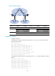
As shown in Figure 51:
• Both CE 1 and CE 2 belong to VPN 1.
• The bandwidth of the link between PE 1 and P is 2 M.
• The bandwidth of the link between PE 2 and P is 2 M.
Provide differentiated QoS services for flows with different precedence values in VPN 1.
The configuration in this example involves the following parts:
First, configure MPLS VPN on CE 1, PE 1, P, PE 2, and CE 2 as follows:
• Run OSPF between PE 1 and P, and between PE 2 and P.
• Form a MP-EBGP neighborship between PE and CE.
• Form a MP-IBGP neighborship between PE and PE.
Second, configure MPLS QoS on PE 1 and P as follows:
• Configure a QoS policy on the incoming interface Ethernet 1/1 on PE 1 and set the EXP field value
for an MPLS packet according to the DSCP attribute of the MPLS packets.
• On the device P, classify traffic on the basis of the EXP field and configure flow-based CBQ:
guarantee 10% of the bandwidth for traffic with an EXP value of 1, guarantee 20% of the bandwidth
for traffic with an EXP value of 2, guarantee 30% of the bandwidth for traffic with an EXP value of
3, and guarantee a low delay and 40% of the bandwidth for traffic with an EXP value of 4.
For the MPLS configuration, see MPLS Configuration Guide. This section introduces only the MPLS QoS
configuration.