
R2511-HP MSR Router Series ACL and QoS Configuration Guide(V5)

53
5. Enter interface view or PVC
view.
• Enter interface view:
interface interface-type interface-number
• Enter PVC view:
a. interface atm interface-number
b. pvc vpi/vci
N/A
6. Apply the PQ list to the
interface.
qos pq pql pql-index
By default, FIFO
applies.
7. Display PQ list
configuration information.
display qos pq interface [ interface-type
interface-number [ pvc { pvc-name [ vpi/vci ] |
vpi/vci } ] ] [ | { begin | exclude | include }
regular-expression ]
Optional.
Available in any view.
8. Display the contents of the
specific PQ list or all the PQ
lists.
display qos pql [ pql-number ] [ | { begin |
exclude | include } regular-expression ]
Optional.
Available in any view.
PQ configuration example
Network requirements
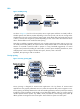
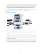
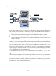
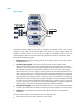
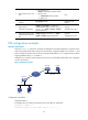
As shown in Figure 20, both Server and Host A send data to Host B through Router A. Suppose Server
sends critical packets and Host A sends non-critical packets. Congestion might occur on Serial 1/1 and
result in packet loss because the rate of the incoming interface Ethernet 1/1 is greater than that of the
outgoing interface Serial 1/1 on Router A.
Configure PQ, so that the critical packets from Server are transmitted preferentially when congestion
occurs in the network.
Figure 20 Network diagram
Configuration procedure
Configure Router A:
# Configure ACLs to match the packets from Server and Host A, respectively.
[RouterA] acl number 2001
[RouterA-acl-basic-2001] rule permit source 1.1.1.1 0.0.0.0
PPP
1.1.1.1/8
1.1.1.2/8
S1/0
Eth1/1
Eth1/1
S1/1
Host A
Host B
Router A
Router B
Server
Ethernet
2M
10M
Ethernet