
R2511-HP MSR Router Series ACL and QoS Configuration Guide(V5)


74
5. Apply the WRED table
to the interface or port
group.
qos wred apply table-name
A queue-based WRED table is available on only
Layer 2 ports.
Configuration example
Apply a queue-based WRED table to Layer 2 port Ethernet 1/1:
# Enter system view.
<Sysname> system-view
# Configure a queue-based WRED table.
[Sysname] qos wred queue table queue-table1
[Sysname-wred-table-queue-table1] quit
# Enter interface view.
[Sysname] interface ethernet 1/1
# Apply the queue-based WRED table to Ethernet 1/1.
[Sysname-Ethernet1/1] qos wred apply queue-table1
Displaying and maintaining WRED
Task Command
Remarks
Display WRED configuration
information on the interface/PVC
or all interfaces/PVCs.
display qos wred interface [ interface-type
interface-number [ pvc { pvc-name [ vpi/vci ]
| vpi/vci } ] ] [ | { begin | exclude |
include } regular-expression ]
Available in any view.
Display configuration information
about a WRED table or all WRED
tables.
display qos wred table [ table-name ] [ |
{ begin | exclude | include }
regular-expression ]
Available in any view.
WRED configuration example
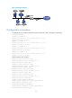
Network requirements
As shown in Figure 23, Server sends critical data traffic, Telephone sends voice traffic, and Host A and
Host B send non-critical data traffic. On Router, because the rate of incoming interface GigabitEthernet
2/1 is higher than that of outgoing interface Ethernet 1/2, congestion might occur on Ethernet 1/2.
Perform configurations to meet the following requirements:
1. Critical traffic from Server and Telephone is transmitted preferentially when congestion occurs in
the network.
2. Certain bandwidth is guaranteed for traffic from Host A and Host B to reduce traffic delay.
3. When congestion deteriorates, packets are dropped based on precedence.
Use WFQ in conjunction with WRED for queue scheduling and packet dropping.