HP MSR Router Series Fundamentals Configuration Guide(V5) Part number: 5998-2018 Software version: CMW520-R2511 Document version: 6PW103-20140128
Legal and notice information © Copyright 2014 Hewlett-Packard Development Company, L.P. No part of this documentation may be reproduced or transmitted in any form or by any means without prior written consent of Hewlett-Packard Development Company, L.P. The information contained herein is subject to change without notice.
Contents Using the CLI ································································································································································ 1 Command conventions ····················································································································································· 1 Using the undo form of a command ·························································································································
Configuring the SSH server on the device ·········································································································· 41 Using the device to log in to an SSH server ······································································································· 43 Local login through the AUX port ································································································································· 43 Configuring none authentication for AUX logi
Enabling displaying the copyright statement ·············································································································· 87 Configuring banners ······················································································································································ 87 Banner message input modes ······························································································································ 87 Configuration procedure
Displaying the contents of a file························································································································· 113 Renaming a file···················································································································································· 113 Copying a file ······················································································································································ 113 Moving a file··
Patch states··························································································································································· 138 Patch installation task list ···································································································································· 140 Installation prerequisites ····································································································································· 140 Installin
Using the CLI At the command-line interface (CLI), you can enter text commands to configure, manage, and monitor your device. Figure 1 CLI example You can log in to the CLI in a variety of ways. For example, you can log in through the console port, or using Telnet or SSH. For more information about login methods, see "Logging in to the CLI." Command conventions Command conventions help you understand the syntax of commands. Commands in product manuals comply with the conventions listed in Table 1.
Figure 2 Understanding command-line parameters For example, to set the system time to 10:30:20, February 23, 2010, enter the following command line at the CLI and press Enter: clock datetime 10:30:20 2/23/2010 Using the undo form of a command Most configuration commands have an undo form for canceling a configuration, restoring the default, or disabling a feature.
Figure 3 CLI view hierarchy Entering system view from user view Task Command Enter system view from user view. system-view Returning to the upper-level view from any view Task Command Return to the upper-level view from any view. quit Executing the quit command in user view terminates your connection to the device. In public key code view, use the public-key-code end command to return to the upper-level view (public key view).
Accessing the CLI online help The CLI online help is context sensitive. You can enter a question mark at any prompt or in any position of a command to display all available options. To access the CLI online help, use one of the following methods: • Enter a question mark at a view prompt to display the first keyword of every command available in the view.
Entering a command When you enter a command, you can use keys or hotkeys to edit the command line, or use abbreviated keywords or keyword aliases. Editing a command line Use the keys listed in Table 2 or the hotkeys listed in Table 3 to edit a command line. Table 2 Command line editing keys Key Function Common keys If the edit buffer is not full, pressing a common key inserts the character at the position of the cursor and moves the cursor to the right.
Configuring and using command keyword aliases The command keyword alias function allows you to replace the first keyword of a non-undo command or the second keyword of an undo command with your preferred keyword when you execute the command. For example, if you configure show as the alias for the display keyword, you can enter show in place of display to execute a display command.
Step Command Remarks By default: • Ctrl+G is assigned the display 2. hotkey { CTRL_G | CTRL_L | CTRL_O | CTRL_T | CTRL_U } command Configure hotkeys. current-configuration command. • Ctrl+L is assigned the display ip routing-table command. • Ctrl+O is assigned the undo debugging all command. • No command is assigned to Ctrl+T or Ctrl+U. 3. display hotkey [ | { begin | exclude | include } regular-expression ] Display hotkeys. Optional. Available in any view.
Hotkey Function Esc+P Moves the cursor up one line. This hotkey is available before you press Enter. Esc+< Moves the cursor to the beginning of the clipboard. Esc+> Moves the cursor to the ending of the clipboard. Enabling redisplaying entered-but-not-submitted commands The redisplay entered-but-not-submitted commands feature enables the system to display what you have typed (except Yes or No for confirmation) at the CLI when your configuration is interrupted by system output such as logs.
Using the command history function The system can automatically save successfully executed commands to the command history buffer for the current user interface. You can view them and execute them again, or set the maximum number of commands that can be saved in the command history buffer. A command is saved to the command history buffer in the exact format as it was entered.
Pausing between screens of output If the output being displayed is more than will fit on one screen, the system automatically pauses after displaying a screen. By default, up to 24 lines can be displayed on a screen. To change the screen length, use the screen-length screen-length command. For more information about this command, see Fundamentals Command Reference. To control output, use keys in Table 5. Table 5 Keys for controlling output Keys Function Space Displays the next screen.
Table 6 Special characters supported in a regular expression Character Meaning Examples ^string Matches the beginning of a line. "^user" matches all lines beginning with "user". A line beginning with "Auser" is not matched. string$ Matches the end of a line. "user$" matches lines ending with "user". A line ending with "userA" is not matched. . Matches any single character, such as a single character, a special character, and a blank. ".s" matches both "as" and "bs".
Character Meaning Examples [^] Matches a single character not contained within the brackets. [^16A] means to match a string containing any character except 1, 6 or A, and the matching string can also contain 1, 6 or A, but cannot contain these three characters only. For example, [^16A] matches "abc" and "m16", but not 1, 16, or 16A. \ Matches a character string ending with string.
# Use | include Vlan in the display ip routing-table command to filter in route entries that contain Vlan. display ip routing-table | include Vlan Routing Tables: Public Destination/Mask Proto Pre 192.168.1.0/24 Direct 0 Cost NextHop Interface 0 192.168.1.42 Vlan999 Configuring user privilege and command levels To avoid unauthorized access, the device defines the user privilege levels and command levels in Table 7. User privilege levels correspond to command levels.
Configuring a user privilege level for users through the AAA module Step Command Remarks 1. Enter system view. system-view N/A 2. Enter user interface view. user-interface { first-num1 [ last-num1 ] | { aux | console | tty | vty } first-num2 [ last-num2 ] } N/A 3. Specify the scheme authentication mode. authentication-mode scheme By default, the authentication mode for VTY and AUX users is password, and no authentication is needed for console and TTY login users. 4. Return to system view.
Step Command Remarks 1. Configure the authentication type for SSH users as publickey. For more information, see Security Configuration Guide. Required only for SSH users who use public-key authentication. 2. Enter system view. system-view N/A 3. Enter user interface view. user-interface { first-num1 [ last-num1 ] | vty first-num2 [ last-num2 ] } N/A 4. Enable the scheme authentication mode.
ssh2 Establish a secure shell client connection super Set the current user priority level telnet Establish one TELNET connection tracert Trace route function # Configure the device to perform no authentication for Telnet users, and to authorize authenticated Telnet users to use level-0 and level-1 commands. (Use no authentication mode only in a secure network environment.
only basic commands like ping and tracert and use a few display commands. The switching operation is effective for the current login. After the user logs in again, the user privilege restores to the original level. To avoid problems, HP recommends that administrators log in with a lower privilege level to view switch operating parameters, and switch to a higher level temporarily only when they must maintain the device.
Step Command Remarks If local authentication is involved, this step is required. 3. Configure the password for the user privilege level. super password [ level user-level ] { cipher | simple } password By default, a privilege level has no password. If no user privilege level is specified when you configure the command, the user privilege level defaults to 3.
User interface authentication mode User privilege level switching authentication mode Information required for the first authentication mode Information required for the second authentication mode local Password configured for the privilege level on the device with the super password command. N/A local scheme Password configured for the privilege level on the device with the super password command. Password for privilege level switching configured on the AAA server.
Task Command Remarks Display data in the clipboard. display clipboard [ | { begin | exclude | include } regular-expression ] Available in any view.
Login overview This chapter describes the available login methods and their configuration procedures. FIPS compliance Table 9 shows the support of devices for the FIPS mode that complies with NIST FIPS 140-2 requirements. Support for features, commands, and parameters might differ in FIPS mode and non-FIPS mode. For more information about FIPS mode, see Security Configuration Guide. Table 9 Hardware and FIPS mode compatibility matrix Hardware FIPS mode MSR900 No. MSR93X No. MSR20-1X No. MSR20 Yes.
Login method Configuration requirements To use SSH service, complete the following configuration tasks: • Logging in through SSH • Enable the SSH server function and configure SSH attributes. • Assign an IP address to a Layer 3 interface and make sure the interface and the SSH client can reach each other. • Enable scheme authentication for VTY login users. • Configure the user privilege level of VTY login users.
User interface assignment The device automatically assigns user interfaces to CLI login users, depending on their login methods. Each user interface can be assigned to only one user at a time. If no user interface is available, a CLI login attempt will be rejected. The maximum number of user interfaces varies by device. For a CLI login, the device always picks the lowest numbered user interface from the idle user interfaces available for the type of login.
Logging in to the CLI By default, the first time you access the CLI you must log in through the console port. At the CLI, you can configure Telnet, SSH, or modem dial-in (through the AUX port) for remote access. Logging in through the console port for the first time To log in through the console port, make sure the console terminal has a terminal emulation program (for example, HyperTerminal in Windows XP).
Figure 5 Connection description Figure 6 Specifying the serial port used to establish the connection 25
Figure 7 Setting the properties of the serial port 5. Power on the device and press Enter at the prompt. Figure 8 CLI 6. At the default user view prompt , enter commands to configure the device or view the running status of the device. To get help, enter ?. Configuring console login control settings The following authentication modes are available for controlling console logins: • None—Requires no authentication. This mode is insecure. • Password—Requires password authentication.
Table 13 Configuration required for different console login authentication modes Authentication mode Configuration tasks Reference None Set the authentication mode to none for the console user interface. "Configuring none authentication for console login" Password Enable password authentication on the console user interface. "Configuring password authentication for console login" Set a password. Enable scheme authentication on the console user interface.
Figure 9 Accessing the CLI through the console port without authentication Configuring password authentication for console login Step Command Remarks 1. Enter system view. system-view N/A 2. Enter console user interface view. user-interface console first-number [ last-number ] N/A 3. Enable password authentication. authentication-mode password By default, you can log in to the device through the console port without authentication and have user privilege level 3 after login. 4.
• To make the command authorization or command accounting function take effect, apply an HWTACACS scheme to the intended ISP domain. This scheme must specify the IP address of the authorization server and other authorization parameters. • If the local authentication scheme is used, use the authorization-attribute level level command in local user view to set the user privilege level on the device.
Step Command Remarks Optional. By default, command accounting is disabled. The accounting server does not record the commands executed by users. 5. Enable command accounting. command accounting 6. Exit to system view. quit Command accounting allows the HWTACACS server to record all commands executed by users, regardless of command execution results. This function helps control and monitor user behaviors on the device.
The next time you attempt to log in through the console port, you must provide the configured login username and password, as shown in Figure 11. Figure 11 Scheme authentication interface for console login Configuring common console user interface settings (optional) Some common settings configured for a console user interface take effect immediately and can interrupt the console login session.
Step Command Remarks The default is 8. The setting depends on the character coding type. For example, you can set it to 7 if standard ASCII characters are to be sent, and set it to 8 if extended ASCII characters are to be sent. 6. Specify the number of data bits in each character. databits { 5 | 6 | 7 | 8 } 7. Define the shortcut key for starting a terminal session. activation-key character By default, you press Enter to start the terminal session. 8. Define a shortcut key for terminating tasks.
Step 15. Set the idle-timeout timer. Command idle-timeout minutes [ seconds ] Remarks The default idle-timeout is 10 minutes. The system automatically terminates the user's connection if there is no information interaction between the device and the user within the idle-timeout time. Setting idle-timeout to 0 disables the idle-timeout function. Logging in through Telnet NOTE: Telnet login is not supported in FIPS mode.
Table 15 Configuration required for different Telnet login authentication modes Authentication mode Configuration tasks Reference None Set the authentication mode to none for the VTY user interface. "Configuring none authentication for Telnet login" Password Enable password authentication on the VTY user interface. Set a password. "Configuring password authentication for Telnet login" Enable scheme authentication on the VTY user interface. Configure local or remote authentication settings.
Figure 13 Telnetting to the device without authentication Configuring password authentication for Telnet login Step Command Remarks 1. Enter system view. system-view N/A 2. Enable Telnet server. telnet server enable N/A 3. Enter one or multiple VTY user interface views. user-interface vty first-number [ last-number ] N/A 4. Enable password authentication. authentication-mode password N/A 5. Set a password.
Figure 14 Password authentication interface for Telnet login Configuring scheme authentication for Telnet login Follow these guidelines when you configure scheme authentication for Telnet login: • To make the command authorization or command accounting function take effect, apply an HWTACACS scheme to the intended ISP domain. This scheme must specify the IP address of the authorization server and other authorization parameters.
Step Command Remarks Optional. 5. Enable command authorization. command authorization By default, command authorization is disabled. The commands available for a user only depend on the user privilege level. If command authorization is enabled, a command is available only if the user has the commensurate user privilege level and is authorized to use the command by the AAA scheme. Optional. By default, command accounting is disabled. The accounting server does not record the commands executed by users.
Step Command Remarks 11. Specify the command level of the local user. authorization-attribute level level Optional. 12. Specify Telnet service for the local user. service-type telnet By default, no service type is specified. 13. Exit to system view. quit N/A 14. Configure common settings for VTY user interfaces. See "Configuring common VTY user interface settings (optional)." Optional. By default, the command level is 0.
Step Command Remarks N/A 2. Enter one or multiple VTY user interface views. user-interface vty first-number [ last-number ] 3. Enable the terminal service. shell Optional. By default, terminal service is enabled. Optional. 4. Enable the user interfaces to support PAD, Telnet, SSH, or all of them. protocol inbound { all | pad | ssh | telnet } By default, all the three protocols are supported. In non-FIPS mode, the device supports PAD, SSH, and Telnet.
Using the device to log in to a Telnet server You can use the device as a Telnet client to log in to a Telnet server. If the server is located in a different subnet than the device, make sure the two devices have routes to reach each other. Figure 16 Telnetting from the device to a Telnet server To use the device to log in to a Telnet server: Step Command Remarks N/A 1. Enter system view. system-view 2. Specify the source IPv4 address or source interface for outgoing Telnet packets.
Table 16 SSH server and client requirements Device role Requirements SSH server Assign an IP address to a Layer 3 interface, and make sure the interface and the client can reach each other. Configure the authentication mode and other settings. SSH client If the host operates as an SSH client, run the SSH client program on the host. Obtain the IP address of the Layer 3 interface on the server.
Step Command Remarks Optional. 7. Enable command authorization. By default, command authorization is disabled. The commands available for a user only depend on the user privilege level. command authorization If command authorization is enabled, a command is available only if the user has the commensurate user privilege level and is authorized to use the command by the AAA scheme. Optional. By default, command accounting is disabled. The accounting server does not record the commands executed by users.
Step Command Remarks 12. Set a password for the local user. password { cipher | simple } password By default, no password is set. 13. Specify the command level of the user. authorization-attribute level level 14. Specify SSH service for the user. service-type ssh By default, no service type is specified. 15. Exit to system view. quit N/A 16. Create an SSH user, and specify the authentication mode for the SSH user.
Figure 19 AUX login diagram To control AUX logins, configure authentication and user privilege for AUX port users. By default, password authentication applies to AUX login, but no login password is configured. To allow AUX login, you must configure a password. The following are authentication modes available for controlling AUX logins: • None—Requires no authentication and is insecure. • Password—Requires a password for accessing the CLI.
Step 4. Configure common settings for AUX login. Command Remarks See "Configuring common settings for AUX login (optional)." Optional. The next time you attempt to log in through the AUX port, you do not need to provide any username or password, as shown in Figure 20. Figure 20 Accessing the CLI through the AUX port without authentication Configuring password authentication for AUX login Step Command Remarks 1. Enter system view. system-view N/A 2. Enter one or more AUX user interface views.
Figure 21 Password authentication interface for AUX login Configuring scheme authentication for AUX login Follow these guidelines when you configure scheme authentication for AUX login: • To make the command authorization or command accounting function take effect, apply an HWTACACS scheme to the intended ISP domain. This scheme must specify the IP address of the authorization server and other authorization parameters.
Step Command Remarks Optional. 4. Enable command authorization. command authorization By default, command authorization is disabled. The commands available for a user only depend on the user privilege level. If command authorization is enabled, a command is available only if the user has the commensurate user privilege level and is authorized to use the command by the AAA scheme. Optional. By default, command accounting is disabled. The accounting server does not record the commands executed by users.
Step Command Remarks 8. Create a local user and enter local user view. local-user user-name N/A 9. Set a password for the local user. password { cipher | simple } password By default, no password is set. Optional. 10. Specifies the command level of the local user. authorization-attribute level level 11. Specify terminal service for the local user. service-type terminal By default, no service type is specified. 12. Configure common AUX user interface settings.
associate Device A's IP address with the Telnet redirect listening port, a user can use the telnet DeviceA-IP-address command to log in to Device B. This Telnet redirect function enables a device to provide Telnet service with its IP address protected. To configure common settings for AUX user interfaces: Step Command Remarks 1. Enter system view. system-view N/A 2. Associate the Telnet redirect listening port with an IP address of the current device.
Step Command Remarks By default, the terminal display type is ANSI. 14. Configure the type of terminal display. terminal type { ansi | vt100 } 15. Configure the user privilege level for login users. user privilege level level 16. Set the maximum number of lines to be displayed on a screen. screen-length screen-length 17. Set the size of command history buffer. history-command max-size value 18. Set the idle-timeout timer.
Step Command Remarks 23. Configure the user interface to change carriage returns 0x0d 0x0a and 0x0d 0x00 received from Telnet clients to 0x0d during redirecting a Telnet connection. redirect return-deal from-telnet By default, the user interface does not change carriage returns received from Telnet clients during redirecting a Telnet connection. 24.
IMPORTANT: • Identify the mark on the console port and make sure you are connecting to the correct port. • The serial ports on PCs do not support hot swapping. If the switch has been powered on, always connect the console cable to the PC before connecting to the switch, and when you disconnect the cable, first disconnect from the switch. Figure 23 Connecting the AUX port to a terminal 3. If the PC is off, turn on the PC. 4.
Figure 25 Specifying the serial port used to establish the connection Figure 26 Setting the properties of the serial port 5. Power on the device and press Enter at the prompt.
Figure 27 CLI 6. At the default user view prompt , enter commands to configure the device or check the running status of the device. To get help, enter ?. Modem dial-in through the AUX port An administrator can use a pair of modems to remotely connect to the device through its AUX port over PSTN when the IP network connection is broken. To do so, make sure the dial-in connection, the device, and the modems are correctly set up. To improve device security, configure AUX login authentication.
Authentication mode Configuration task Reference Enable scheme authentication on the AUX user interface. Configure local or remote authentication settings. To configure local authentication: 27. Configure a local user and specify the password. Scheme 28. Configure the device to use local authentication. To configure remote authentication: 29. Configure the RADIUS or HWTACACS scheme on the device. "Configuring scheme authentication for modem dial-in" 30.
6. Launch the terminal emulation program on the PC and create a connection using the telephone number of the modem connected to the device. Figure 29 to Figure 30 shows the configuration procedure in Windows XP HyperTerminal. On Windows Server 2003, add the HyperTerminal program first, and then log in to and manage the device as described in this document.
Figure 31 Dialing the number Character string CONNECT9600 is displayed on the terminal. 8. Press Enter as prompted. Figure 32 Login page 9. At the default user view prompt , enter commands to configure the device or check the running status of the device. To get help, enter ?. IMPORTANT: Do not directly close the HyperTerminal. Doing so can cause some modems to stay in use, and your subsequent dial-in attempts will always fail.
Configuring none authentication for modem dial-in Step Command Remarks 1. Enter system view. system-view N/A 2. Enter one or more AUX user interface views. user-interface aux first-number [ last-number ] N/A 3. Enable none authentication mode. authentication-mode none N/A 4. Configure common settings for the AUX user interfaces. See "Configuring common settings for modem dial-in (optional)." Optional.
The next time you attempt to dial in to the device, you must provide the configured login password, as shown in Figure 34. Figure 34 Password authentication interface for modem dial-in users Configuring scheme authentication for modem dial-in Follow these guidelines when you configure scheme authentication for AUX login: • To make the command authorization or command accounting function take effect, apply an HWTACACS scheme to the intended ISP domain.
Step Command Remarks Optional. 4. Enable command authorization. By default, command authorization is disabled. The commands available for a user only depend on the user privilege level. command authorization If command authorization is enabled, a command is available only if the user has the commensurate user privilege level and is authorized to use the command by the AAA scheme. Optional. By default, command accounting is disabled. The accounting server does not record the commands executed by users.
Step 8. 9. Command Remarks Create a local user and enter local user view. local-user user-name N/A Set a password for the local user. password { cipher | simple } password By default, no password is set. Optional. 10. Specify the command level of the local user. authorization-attribute level level 11. Specify terminal service for the local user. service-type terminal By default, no service type is specified. 12. Configure common AUX user interface settings.
IMPORTANT: To avoid packet loss, make sure the speed of the AUX port is slower than the transmission rate of the modem. You can connect a device (Device B) to the AUX port of the current device (Device A), and configure the current device to redirect a Telnet login user to that device. If the redirect enable and redirect listen-port port-number commands are configured, a user can use the telnet DeviceA-IP-address port-number command to log in to Device B.
Step Command flow-control { hardware | none | software } 13. Configure the flow control mode. flow-control hardware flow-control-type1 [ software flow-control-type2 ] flow-control software flow-control-type1 [ hardware flow-control-type2 ] Remarks The default is as follows: • Independent AUX port—Hardware flow control. • Console and AUX integrated port—Off. By default, the terminal display type is ANSI. The device supports two types of terminal display: ANSI and VT100.
Step Command Remarks 22. Enable Telnet redirect for the current user interface. redirect enable By default, the redirect function is disabled. 23. Specify a Telnet redirect listening port. redirect listen-port port-number The default port number is the absolute user interface number plus 2000. 24. Disable Telnet option negotiation during redirecting a Telnet connection. redirect refuse-negotiation By default, Telnet option negotiation is enabled.
Task Command Remarks Display user interface information. display user-interface [ num1 | { aux | console | tty | vty } num2 ] [ summary ] [ | { begin | exclude | include } regular-expression ] Available in any view. Display the configuration of the device when it serves as a Telnet client. display telnet client configuration [ | { begin | exclude | include } regular-expression ] Available in any view. Available in user view. Release a user interface.
Logging in to the Web interface The device provides a built-in Web server for you to configure the device through a Web browser. The device supports HTTP 1.0 and HTTPS for transferring webpage data across the Internet. HTTPS uses SSL to encrypt data between the client and the server for data integrity and security, and is more secure than HTTP. You can define a certificate attribute-based access control policy to allow only legal clients to access the device.
Step Command Remarks Optional. 4. Configure the HTTP service port number. The default HTTP service port is 80. ip http port port-number If you execute the command multiple times, the most recent configuration takes effect. Optional. By default, the HTTP service is not associated with any ACL. 5. Associate the HTTP service with an ACL. ip http acl acl-number 6. Set the Web connection timeout time. web idle-timeout minutes Optional. 7. Set the size of the buffer for Web login logging.
• If the HTTPS service and the SSL VPN service use the same port number, they must have the same SSL server policy. Otherwise, only one of the two services can be enabled. • If the HTTPS service and the SSL VPN service use the same port number and the same SSL server policy, disable the two services before you modify the SSL server policy, and re-enable them after the modification. Otherwise, the SSL server policy does not take effect. To configure HTTPS login: Step Command Remarks Optional. 1.
Step Command Remarks Optional. By default, the HTTPS service is not associated with any certificate-based attribute access control policy. 5. Associate the HTTPS service with a certificate attribute-based access control policy. ip https certificate access-control-policy policy-name Associating the HTTPS service with a certificate-based attribute access control policy enables the device to control the access rights of clients.
Step Command Remarks 12. Configure a password for the local user. password { cipher | simple } password By default, no password is configured for the local user. 13. Specify the command level of the local user. authorization-attribute level level By default, no command level is configured for the local user. 14. Specify the Web service type for the local user. service-type web By default, no service type is configured for the local user. 15. Exit to system view. quit N/A 16.
system-view [Sysname] interface ethernet1/1 [Sysname-Ethernet1/1] ip address 192.168.0.58 255.255.255.0 [Sysname-Ethernet1/1] quit # Create a local user named admin, and set the password to admin for the user. Specify the Web service type for the local user, and set the command level to 3 for this user. [Sysname] local-user admin [Sysname-luser-admin] service-type web [Sysname-luser-admin] authorization-attribute level 3 [Sysname-luser-admin] password simple admin 2.
Configuration procedure This example assumes that the CA is named new-ca, runs Windows Server, and is installed with the SCEP add-on. This example also assumes that the device, host, and CA can reach one other. 1. Configure the device (HTTPS server): # Configure a PKI entity, configure the common name of the entity as http-server1, and the FQDN of the entity as ssl.security.com. system-view [Device] pki entity en [Device-pki-entity-en] common-name http-server1 [Device-pki-entity-en] fqdn ssl.
# Associate the HTTPS service with certificate attribute-based access control policy myacp. [Device] ip https certificate access-control-policy myacp # Enable the HTTPS service. [Device] ip https enable # Create a local user named usera, set the password to 123, specify the Web service type, and specify the user privilege level 3. A level-3 user can perform all operations supported by the device.
Logging in through SNMP You can run SNMP on an NMS to access the device MIB and perform GET and SET operations to manage and monitor the device. The device supports SNMPv1, SNMPv2c, and SNMPv3, and can work with various network management software products, including IMC. For more information about SNMP, see Network Management and Monitoring Configuration Guide. NOTE: SNMP is not supported in FIPS mode.
Step 3. 4. Command Remarks Configure an SNMP group and specify its access right. snmp-agent group v3 group-name [ authentication | privacy ] [ read-view read-view ] [ write-view write-view ] [ notify-view notify-view ] [ acl acl-number | acl ipv6 ipv6-acl-number ] * By default, no SNMP group is configured. Add a user to the SNMP group.
NMS login example Network requirements Configure the device and network management station so you can remotely manage the device through SNMPv3. Figure 40 Network diagram Configuration procedure 1. Configure the device: # Assign an IP address to the device. Make sure the device and the NMS can reach each other. (Details not shown.) # Enter system view. system-view # Enable the SNMP agent. [Sysname] snmp-agent # Configure an SNMP group.
Controlling user logins Use ACLs to prevent unauthorized logins. For more information about ACLs, see ACL and QoS Configuration Guide. Controlling Telnet logins Use a basic ACL (2000 to 2999) to filter Telnet traffic by source IP address. Use an advanced ACL (3000 to 3999) to filter Telnet traffic by source and/or destination IP address. Use an Ethernet frame header ACL (4000 to 4999) to filter Telnet traffic by source MAC address.
Step Command Remarks Create an advanced ACL and enter its view, or enter the view of an existing advanced ACL. acl [ ipv6 ] number acl-number [ name name ] [ match-order { config | auto } ] By default, no advanced ACL exists. 3. Configure an ACL rule. rule [ rule-id ] { permit | deny } rule-string N/A 4. Exit advanced ACL view. quit N/A 5. Enter user interface view. user-interface [ type ] first-number [ last-number ] N/A 6. Apply the ACL to the user interfaces.
Figure 41 Network diagram Configuration procedure # Configure basic ACL 2000, and configure rule 1 to permit packets sourced from Host B, and rule 2 to permit packets sourced from Host A. system-view [Sysname] acl number 2000 match-order config [Sysname-acl-basic-2000] rule 1 permit source 10.110.100.52 0 [Sysname-acl-basic-2000] rule 2 permit source 10.110.100.
Step Command Remarks • SNMPv1/v2c community: snmp-agent community { read | write } community-name [ mib-view view-name ] [ acl acl-number | acl ipv6 ipv6-acl-number ] * • SNMPv1/v2c group: snmp-agent group { v1 | v2c } group-name [ read-view read-view ] [ write-view write-view ] [ notify-view notify-view ] [ acl acl-number | acl ipv6 ipv6-acl-number ] * • SNMPv3 group: 5. Apply the ACL to an SNMP community, group, or user.
[Sysname] acl number 2000 match-order config [Sysname-acl-basic-2000] rule 1 permit source 10.110.100.52 0 [Sysname-acl-basic-2000] rule 2 permit source 10.110.100.46 0 [Sysname-acl-basic-2000] quit # Associate the ACL with the SNMP community and the SNMP group.
Figure 43 Network diagram Host A 10.110.100.46 IP network Device Host B 10.110.100.52 Configuration procedure # Create ACL 2000, and configure rule 1 to permit packets sourced from Host B. system-view [Sysname] acl number 2030 match-order config [Sysname-acl-basic-2030] rule 1 permit source 10.110.100.52 0 # Associate the ACL with the HTTP service so only the Web users on Host B can access the device.
Managing the device The following matrix shows the storage media supported on different router models: Hardware Supported storage media MSR900 • Flash memory • USB disk MSR93X • Flash memory • USB disk MSR20-1X • Flash memory • USB disk MSR20 • CF card • USB disk MSR30 • Flash memory (supported by the MSR30-10, MSR30-11E, and MSR30-11F) • CF card (supported by the MSR30-16, MSR30-20, MSR30-40, and MSR30-60) • USB disk MSR50 • Flash memory (not supported by the MPUF) • CF card • USB disk MSR100
Changing the system time You must synchronize your device with a trusted time source by using NTP or changing the system time before you run it on the network. Network management depends on an accurate system time setting, because the timestamps of system messages and logs use the system time. For NTP configuration, see Network Management and Monitoring Configuration Guide. In a small-sized network, you can manually set the system time of each device.
Command Effective system time Configuration example date-time outside the daylight saving time range: clock datetime 1:00 2007/1/1 clock summer-time ss one-off 1:00 2006/1/1 1:00 2006/8/8 2 date-time System time 01:00:00 UTC Mon 01/01/2007 10:00:00 ss Mon 01/01/2007 1, 3 date-time in the daylight saving time range: date-time + summer-offset 3, 1 (date-time in the daylight saving time range) clock summer-time ss one-off 1:00 2007/1/1 1:00 2007/8/8 2 clock summer-time ss one-off 1:00 2007/1/1 1:00 2
Command Effective system time Configuration example System time clock datetime 1:00 2007/1/1 date-time ± zone-offset outside the daylight saving time range: clock timezone zone-time add 1 clock summer-time ss one-off 1:00 2008/1/1 1:00 2008/8/8 2 date-time ± zone-offset 1, 2, 3 or 1, 3, 2 02:00:00 zone-time Mon 01/01/2007 clock datetime 1:00 2007/1/1 date-time ± zone-offset outside the daylight saving time range: clock timezone zone-time add 1 date-time ± zone-offset + summer-offset clock summe
Step Command Remarks • Set a non-recurring scheme: Set a daylight saving time scheme. 4. clock summer-time zone-name one-off start-time start-date end-time end-date add-time • Set a recurring scheme: clock summer-time zone-name repeating start-time start-date end-time end-date add-time Optional. Use either command. By default, daylight saving time is disabled, and the UTC time zone applies.
keywords and the delimiters cannot exceed 510 characters. In this mode, do not press Enter before you input the end delimiter. For example, you can configure the shell banner "Have a nice day." as follows: system-view [System] header shell %Have a nice day.% Multiple-line input • Input message text in multiple lines. With this method, the message text can be up to 2000 characters.
Configuring the maximum number of concurrent users You can configure this command to limit the number of users that can enter the system view simultaneously. When the number of concurrent users reaches the upper limit, other users cannot enter system view. When multiple users configure a setting in system view, the most recent configuration applies. To configure the maximum number of concurrent users: Step 1. Enter system view. 2. Configure the maximum number of concurrent users.
• Reboot the device immediately at the CLI. • At the CLI, schedule a reboot to occur at a specific time and date or after a delay. • Power off and then power on the device. This method might cause data loss, and is the least-preferred method. Reboot at the CLI enables easy remote device maintenance. Rebooting devices immediately at the CLI To reboot a device, execute the following command in user view: Task Command Reboot a subcard or the device immediately.
Job configuration methods You can configure jobs by using the non-modular or modular method. Use the non-modular method for a one-time command execution and use non-modular method for complex maintenance work.
Scheduling a job by using the non-modular method To schedule a job, execute one of the following commands in user view: Task Command • Schedule a job to run a Schedule a job. command at a specific time: schedule job at time [ date ] view view command • Schedule a job to run a command after a delay: schedule job delay time view view command Remarks Use either command. NOTE: • If you execute the schedule job command multiple times, the most recent configuration takes effect.
Figure 44 Network diagram Configuration procedure # Enter system view. system-view # Create a job named pc1, and enter its view. [Sysname] job pc1 # Configure the job to be executed in the view of Ethernet 1/1. [Sysname-job-pc1] view ethernet 1/1 # Configure the device to enable Ethernet 1/1 at 8:00 on working days every week.
# Configure the device to shut down Ethernet 1/3 at 18:00 on working days every week. [Sysname-job-pc3] time 2 repeating at 18:00 week-day mon tue wed thu fri command shutdown [Sysname-job-pc3] quit # Display information about scheduled jobs.
Figure 45 Handling console login password loss Console login password lost Reboot the device to access the extended Boot ROM menu Y Password recovery capability enabled? Skip Current System Configuration N Restore to Factory Default Configuration Skip Authentication for Console Login Reboot the device Configure new password in system view Save the running configuration To disable password recovery capability: Step Command Remarks 1. Enter system view. system-view N/A 2.
Feature MSR900 MSR93X MSR20-1X MSR20 MSR30 MSR50 MSR1000 Configure temperature thresholds for a card No No No Yes Yes Yes No You can set the temperature threshold to monitor the temperature of a card. When the temperature reaches the thresholds, the device generates alarms. To configure the temperature thresholds: Step Command Remarks 1. Enter system view. system-view N/A 2. Configure the temperature threshold for a card.
To monitor NMS-connected interfaces: Step 1. Enter system view. Command Remarks system-view N/A • Specify the primary interface: Configure at least one command. nms primary monitor-interface interface-type interface-number 2. Specify NMS-connected interfaces. • Specify the secondary interface: nms secondary monitor-interface interface-type interface-number By default, no interfaces are configured as NMS-connected interfaces to be monitored.
Ethernet packet transmission by switching the interface card to operate in EFM mode, thus protecting user investment and improving packet transmission speed by avoiding ATM devices from converting packets between Ethernet packets and ATM cells. 3G modem (PPP/Ethernet)—Supports switching between PPP mode and Ethernet mode. In PPP mode, the link layer protocol is PPP and the network layer protocol is IP. In Ethernet mode, the link layer protocol is Ethernet and the network layer protocol is IP.
Verifying transceiver modules You can verify the genuineness of a transceiver module in the following ways: • Display the key parameters of a transceiver module, including its transceiver type, connector type, central wavelength of the transmit laser, transfer distance and vendor name. • Display its electronic label. The electronic label is a profile of the transceiver module and contains the permanent configuration including the serial number, manufacturing date, and vendor name.
Disabling the USB ports Before you disable the USB ports, make sure the USB ports are not being used for data read/write operation. Otherwise, the operation might fail. Disabling the USB ports also disables the USB-based storage and 3G functions. To disable the USB ports: Task Command Remarks Disable the USB ports usb disable Available in system view.
Task Command Remarks Display or save running status data for multiple feature modules. display diagnostic-information [ | { begin | exclude | include } regular-expression ] Available in any view. Display CPU usage statistics. display cpu-usage [ entry-number [ offset ] [ verbose ] [ from-device ] ] [ | { begin | exclude | include } regular-expression ] Available in any view. Display historical CPU usage statistics in charts.
Managing configuration files You can manage configuration files at the CLI or by using the Boot menu of the device. This chapter describes only managing configuration files from the CLI. Overview A configuration file saves configurations as a set of text commands. You can save the running configuration to a configuration file so the configuration takes effect after you reboot the device. You can also back up the configuration file on to a host and download the file to the device as needed.
• Commands are saved in their complete form. • The commands are listed in sections by view, typically in this order: system view, interface view, protocol views, and user interface view. • Sections are separated with one or more blank lines or comment lines that start with a pound sign (#). • A configuration file ends with the word return. You can execute the save command to save the running configuration to a configuration file.
Hardware FIPS mode MSR30 Yes (except the MSR30-16). MSR50 Yes. MSR1000 Yes. Saving the running configuration To make configuration changes take effect at the next startup, save the running configuration to the startup configuration file to be used at the next startup before the device reboots. Complete the following tasks to save the running configuration: Task Remarks Optional.
process, the next-startup configuration file is lost. You must re-specify a new startup configuration file after the device reboots (see "Specifying a configuration file for the next startup"). • Safe mode—Use the save command with the safely keyword. Safe mode is slower than fast mode, but more secure. In safe mode, the system saves configuration in a temporary file and starts overwriting the target next-startup configuration file after the save operation is complete.
• Overwrite the configuration file—The system uses the running configuration to overwrite the old configuration file on the device without backing up the file. Make sure the storage medium has enough space for the backup configuration file and the new next-startup configuration file. To load the backup configuration file after a software downgrade, specify the backup file as the next-startup configuration file.
Step Command Remarks 1. Create the configuration archive directory. See "Managing the file system." N/A 2. Enter system view. system-view N/A By default, no path or file name prefix is set for configuration archives, and the system does not regularly save configuration. IMPORTANT: Configure the directory and file name prefix for archiving the running configuration. 3.
Manually archiving running configuration To save system resources, disable automatic configuration archiving and manually archive configuration if the configuration will not be changed very often. You can also manually archive configuration before performing complicated configuration tasks so you can use the archive for configuration recovery after the configuration attempt fails. Make sure you have set an archive path and file name prefix before performing this task.
Task Command Remarks Specify the startup configuration file to be used at the next startup. startup saved-configuration cfgfile [ backup | main ] The configuration file must use the .cfg extension and be saved in the root directory of storage media. Backing up the next-startup configuration file to a TFTP server Before performing this task, make sure the server is reachable and enabled with TFTP service, and you have read and write permissions.
Deleting a next-startup configuration file CAUTION: This task permanently deletes the next-startup configuration file from the device. Before performing this task, back up the file as needed. You can delete the main, the backup, or both. If the main and backup next-startup configuration files are the same file, the system sets the attribute of the configuration file to NULL instead of deleting the file. You can permanently delete the file after its attribute changes to NULL.
Managing the file system The following matrix shows the storage media supported on different router models: Hardware Storage media MSR900 • Flash • USB disk MSR93X • Flash • USB disk MSR20-1X • Flash • USB disk MSR20 • CF card • USB disk MSR30 • Flash (supported on MSR30-10, MSR30-11E, and MSR30-11F) • CF card (supported on MSR30-16, MSR30-20, MSR30-40, and MSR30-60) • USB disk MSR50 • Flash (unsupported only on MPUF) • CF card • USB disk MSR1000 • Flash • USB disk Overview This chapter desc
Format Description Length Example 1 to 135 characters test/a.cfg indicates a file named a.cfg in the test folder in the current working directory. 1 to 135 characters flash:/test/a.cfg indicates a file named a.cfg in the test folder in the root directory of the Flash memory. Specifies a file in a specific folder in the current working directory. path/file-name The path argument represents the path to the file. If the file is in a single-level folder, specify the folder name for the argument.
The copy operation enables you to create a file. You can also create a file by performing the download operation or using the save command. Displaying file information Perform this task in user view. Task Command Display file or directory information. dir [ /all ] [ file-url | /all-filesystems ] Displaying the contents of a file Perform this task in user view. Task Command Remarks Display the contents of a file.
A file in the recycle bin occupies storage space. To release the occupied space, execute the reset recycle-bin command in the directory that holds the file. To save storage space, periodically empty the recycle bin with the reset recycle-bin command. Perform the following tasks in user view: Task Command Delete a file by moving it to the recycle bin. delete file-url Restore a file from the recycle bin. undelete file-url Delete a file permanently.
Task Command Display the current working directory. pwd Changing the current working directory Perform this task in user view. Task Command Change the current working directory. cd { directory | .. | / } Creating a directory Perform this task in user view. Task Command Create a directory. mkdir directory Removing a directory To remove a directory, you must delete all files and subdirectories in this directory. To delete a file, use the delete command.
To manage the space of a storage medium, perform one of the following tasks in user view: Task Command Remarks Repair a storage medium. fixdisk device N/A Format a storage medium. format device [ FAT16 | FAT32 ] FAT16 and FAT32 are not applicable to a Flash. Mounting and unmounting a storage medium The following matrix shows the feature and router compatibility: Hardware Feature compatible MSR900 Yes. MSR93X Yes. MSR20-1X Yes. MSR20 Yes. MSR30 Yes. MSR50 Yes. MSR1000 Yes.
Task Command Remarks Mount a storage medium. mount device By default, a storage medium is automatically mounted and in mounted state when connected to the system. Unmount a storage medium. umount device By default, a storage medium is automatically mounted and in mounted state when connected to the system. Displaying and maintaining the NAND Flash memory The following matrix shows the feature and router compatibility: Hardware NAND Flash memory compatible MSR900 No. MSR93X Yes. MSR20-1X No.
Task Command Display data on the specified physical page. display nandflash page-data page-value [ | { begin | exclude | include } regular-expression ] Performing batch operations A batch file comprises a set of executable commands. Executing a batch file is the same as executing the commands one by one. However, execution of a batch file does not guarantee successful execution of every command in the batch file.
19540 KB total (2521 KB free) # Create new folder mytest in the test directory. cd test mkdir mytest %Created dir flash:/test/mytest. # Display the current working directory. pwd flash:/test # Display the files and the subdirectories in the test directory. dir Directory of flash:/test/ 0 drw- - Feb 16 2006 15:28:14 2540 KB total (2519 KB free) # Return to the upper directory. cd .. # Display the current working directory.
Configuring FTP NOTE: FTP is not supported in FIPS mode. File Transfer Protocol (FTP) is an application layer protocol based on the client/server model. It is used to transfer files from one host to another over a TCP/IP network. FTP server uses TCP port 20 to transfer data and TCP port 21 to transfer control commands. For more information about FTP, see RFC 959. FTP supports the following transfer modes: • Binary mode—Used to transfer image files, such as .bin and .btm files.
Using the device as an FTP client To connect to an FTP server or enter FTP client view, make sure the following requirements are met: • You have level-3 (Manage) user privileges on the device. In FTP client view, whether a directory or file management command can be successfully executed depends on the authorization set on the FTP server. • The device and the FTP server can reach each other. • You have a user account (including the username, password, and authorization) on the FTP server.
Step Command Remarks • (Method 1) Log in to the remote FTP 4. Log in to the remote FTP server. server in user view: ftp [ server-address [ service-port ] [ vpn-instance vpn-instance-name ] [ source { interface interface-type interface-number | ip source-ip-address } ] ] Use either method. • (Method 2) Log in to the remote FTP server in FTP client view: a. ftp b.
Working with the files on the FTP server After you log in to the server, you can upload a file to or download a file from the authorized directory by following these steps: 1. Use the dir or ls command to display the directory and the location of the file on the FTP server. 2. Delete unused files to get more free storage space. 3. Set the file transfer mode. FTP transmits files in two modes: ASCII and binary. Use ASCII mode to transfer text files. Use binary mode to transfer image files. 4.
Maintaining and troubleshooting the FTP connection Task Command Remarks Display the help information of FTP-related commands on the FTP server. remotehelp [ protocol-command ] N/A Enable information display in a detailed manner. verbose By default, the function is enabled. Enable FTP related debugging when the device acts as the FTP client. debugging By default, the function is disabled.
Press CTRL+K to abort Connected to 10.1.1.1 220 WFTPD 2.0 service (by Texas Imperial Software) ready for new user User(10.1.1.1:(none)):abc 331 Give me your password, please Password: 230 Logged in successfully # Set the file transfer mode to binary. [ftp] binary 200 Type set to I. # Download the system software image file newest.bin from the PC to the device. [ftp] get newest.bin 227 Entering Passive Mode (10,1,1,1,10,68). 125 BINARY mode data connection already open, transfer starting for /newest.bin.
NOTE: When you use the Internet Explorer browser to log in to the device operating as an FTP server, some FTP functions are not available. This is because multiple connections are required during the login process but the device supports only one connection at a time.
Remote authentication—The device sends the client's username and password to a remote authentication server for authentication. The user account is configured on the remote authentication server rather than the device. • To assign an FTP user write access (including upload, delete, and create) to the device, assign level-3 (Manage) user privileges to the user. For read-only access to the file system, any user privilege level is OK.
# Create a local user account abc, set its password to abc and the user privilege level to level 3 (the manage level), specify the root directory of the Flash as the authorized directory, and specify the service type as FTP.
NOTE: After you finish transferring the Boot ROM image through FTP, execute the bootrom update command to upgrade Boot ROM. 3. Upgrade the device: # Specify newest.bin as the main system software image file for the next startup. boot-loader file newest.bin main IMPORTANT: The system software image file used for the next startup and the startup configuration file must be saved in the root directory of the storage medium. You can copy or move the file to the root directory.
Configuring TFTP NOTE: TFTP is not supported in FIPS mode. Trivial File Transfer Protocol (TFTP) is a simplified version of FTP for file transfer over secure reliable networks. TFTP uses UDP port 69 for connection establishment and data transmission. In contrast to TCP-based FTP, TFTP requires no authentication or complex message exchanges, and is easier to deploy. TFTP supports the following transfer modes: • Binary mode—Used to transfer image files, such as .bin and .btm files.
Using the device as a TFTP client The device provides the following modes for downloading a new file from a TFTP server: • Normal download—The new file is written directly to the storage medium and overwrites the old file that has the same name as it. If file download is interrupted, both old and new files are lost. • Secure download—The new file is downloaded to memory and will not be written to the storage medium until the whole file is obtained.
Step Command Remarks • For IPv4: tftp server-address { get | put | sget } source-filename [ destination-filename ] [ vpn-instance vpn-instance-name ] [ source { interface interface-type interface-number | ip source-ip-address } ] Download or upload a file. 5. Optional.
# Examine the storage medium of the device for insufficiency or impairment. If no sufficient free space is available, use the fixdisk command to fix the storage medium or use the delete/unreserved file-url command to delete unused files. (Details not shown.) # Download system software image file newest.bin from the PC. tftp 1.2.1.1 get newest.bin # Upload a configuration file config.cfg to the TFTP server. tftp 1.2.1.1 put config.cfg configback.cfg # Specify newest.
Managing licenses License compliance Table 28 shows the support of devices for the license feature. Table 28 Hardware and license compatibility matrix Hardware License MSR900 No MSR93X No MSR20-1X No MSR20 Yes MSR30 Yes MSR50 Yes (Only supported by MPU-G2) MSR1000 No Registering the software The system software comes with a trial period. You must register the software within its trial period.
Upgrading software You can use the CLI or Boot menu to upgrade software. This chapter describes only upgrading the software and installing hotfixes from the CLI. Upgrading software includes upgrading the BootWare (called "bootrom" in CLI) and system software.
Hardware FIPS mode MSR30 Yes (except the MSR30-16). MSR50 Yes. Software upgrade methods You can use one of the following methods to upgrade software: Upgrading method Software types Remarks Upgrading from the CLI: Upgrading software Installing hotfixes Upgrading from the Boot menu • BootWare image • System software image (excluding patches) System software images • BootWare image • System software images You must reboot the device to complete the upgrade.
Upgrading system software Step 1. Use FTP or TFTP to transfer the system software image to the root directory of the device's storage media. Command Remarks See "Configuring FTP" or "Configuring TFTP." The image file must be saved in the root directory for a successful upgrade. 2. Specify the file as the startup system software image in user view.
Patch states A patch is in IDLE, DEACTIVE, ACTIVE, or RUNNING state, depending on the patch manipulation command. Patch manipulation commands include patch load (load), patch active (run temporarily), patch run (confirm running), patch deactive (stop running), patch delete (delete), patch install (install), and undo patch install (uninstall). For example, if you execute the patch active command, patches in DEACTIVE state change to the ACTIVE state.
Figure 53 Patches that are not loaded to the patch memory area DEACTIVE state Patches in DEACTIVE state have been loaded to the patch memory area but have not yet run in the system. Suppose that the patch file you are loading has seven patches. After the seven patches successfully pass the version check and CRC check, they are loaded to the patch memory area and are in DEACTIVE state. In the patch memory area, patch states are as shown in Figure 54.
Figure 55 Patches are activated RUNNING state After you confirm ACTIVE patches, their state changes to RUNNING and persists after a reboot. In contrast to ACTIVE patches, RUNNING patches continue to take effect after a reboot. For example, if you confirm the first three patches in Figure 55, their state changes from ACTIVE to RUNNING, and the RUNNING state persists after a reboot. The patch states of the system are shown in Figure 56.
• Save the patch file or the patch package file to the root directory of the device's storage media. • Correctly name a patch file in the patch_PATCH-FlAG suffix.bin format. The PATCH-FLAG suffix is pre-defined, and must be the same as the first three characters of the value for the Version field in the output from the display patch information command. If the patch file is not correctly named, the system cannot identify the file. The default system patch file name of the device is patch_main.bin.
Task Remarks Loading a patch file Required. Activating patches Required. Confirming ACTIVE patches Optional. Configuring the patch file location The patch file location must be the root directory of a storage medium. If the device has only one storage medium, you do not need to perform this task. To configure the patch file location: Step 1. 2. Enter system view. Configure the patch file location.
Activating patches Activating a patch changes its state to ACTIVE. An ACTIVE patch runs in memory until a reboot occurs. To have a patch continue to run after a reboot, you must change its state to RUNNING. To activate patches: Step Command 1. Enter system view. system-view 2. Activate patches. patch active [ patch-number ] Confirming ACTIVE patches To have an ACTIVE patch continue to run after a reboot, perform the task in this section.
Displaying and maintaining software upgrade Task Command Remarks Display information about the system software image. display boot-loader [ | { begin | exclude | include } regular-expression ] Available in any view. Display information about the patch package. display patch [ | { begin | exclude | include } regular-expression ] Available in any view. Display patch information. display patch information [ | { begin | exclude | include } regular-expression ] Available in any view.
[FTP-Server-luser-aaa] authorization-attribute work-directory flash:/aaa 2. Configure the device: # Log in to the FTP server. ftp 2.2.2.2 Trying 2.2.2.2 ... Press CTRL+K to abort Connected to 2.2.2.2. 220 WFTPD 2.0 service (by Texas Imperial Software) ready for new user User(2.2.2.2:(none)):aaa 331 Give me your password, please Password: 230 Logged in successfully # Download new-config.cfg from the FTP server. [ftp] ascii [ftp] get new-config.cfg # Download soft-version2.
# Save the patch file patch_xxx.bin to the directory of the TFTP server. (Details not shown.) 2. Configure the device: # Use the save command to save the running configuration. (Details not shown.) # Examine the space of the Flash on the device. If the free space is not sufficient for the patches, delete unused files to release space. (Details not shown.) # Download patch_xxx.bin from the TFTP server to the root directory of the device's storage media. tftp 2.2.2.2 get patch_xxx.
Automatic configuration Automatic configuration enables a device without any configuration file to automatically obtain and execute a configuration file during startup. Automatic configuration simplifies network configuration, facilitates centralized management, and reduces maintenance workload. To implement automatic configuration, the network administrator saves configuration files on a server and a device automatically obtains and executes a specific configuration file.
How automatic configuration operates 1. During startup, the device sets the first interface in up state as the DHCP client to request parameters from the DHCP server, such as an IP address and name of a TFTP server, IP address of a DNS server, and the configuration file name. If there are Layer 2 Ethernet interfaces in up state, the VLAN interface of the default VLAN of the Ethernet interfaces is selected as the first up interface.
Using DHCP to obtain an IP address and other configuration information Address acquisition process As mentioned in "How automatic configuration operates," a device sets the first up interface as the DHCP client during startup. The DHCP client broadcasts a DHCP request, where the Option 55 field specifies the information the client wants to obtain from the DHCP server such as the configuration file name, domain name and IP address of the TFTP server, and DNS server IP address.
To configure static address pools, you must obtain corresponding client IDs. To obtain a device's client ID, use the display dhcp server ip-in-use command to display address binding information on the DHCP server after the device obtains its IP address through DHCP. Obtaining the configuration file from the TFTP server A device can obtain the following files from the TFTP server during automatic configuration: • The configuration file specified by the Option 67 or file field in the DHCP response.
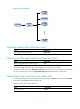
Obtaining the configuration file Figure 61 Obtaining the configuration file A device obtains its configuration file by using the following work flow: • If the DHCP response contains the configuration file name, the device requests the specified configuration file from the TFTP server. • If not, the device tries to get its host name from the host name file obtained from the TFTP server. If it fails, the device resolves its IP address to the host name through DNS server.
• If the IP address and the domain name of the TFTP server are not contained in the DHCP response or they are illegitimate, the device broadcasts a TFTP request. After broadcasting a TFTP request, the device selects the TFTP server that responds first to obtain the configuration file. If the requested configuration file does not exist on the TFTP server, the request operation fails, and the device removes the temporary configuration and starts up with factory defaults.
4. During the reboot, the device checks whether all commands in the main startup configuration file are executed successfully. If yes, the automatic configuration succeeds. If not, the automatic configuration fails, and the device writes a log entry to a log file that is named autodeploy.cfg.log and saved in the root directory of the USB disk. Figure 62 Automatic configuration from a USB disk Device powered on (with usba0) Found device serial number.
The USB disk for automatic configuration must be inserted to the device before the device starts up. The configuration file intended for automatic configuration must meet the following requirements: • Be named in the format device serial number.cfg or xxx.autodeploy.cfg, or use the name autodeploy.cfg. • Be saved in the root directory of usba0. If the configuration file intended for automatic configuration is named in the format xxx.autodeploy.
Support and other resources Contacting HP For worldwide technical support information, see the HP support website: http://www.hp.
Conventions This section describes the conventions used in this documentation set. Command conventions Convention Description Boldface Bold text represents commands and keywords that you enter literally as shown. Italic Italic text represents arguments that you replace with actual values. [] Square brackets enclose syntax choices (keywords or arguments) that are optional. { x | y | ... } Braces enclose a set of required syntax choices separated by vertical bars, from which you select one.
Network topology icons Represents a generic network device, such as a router, switch, or firewall. Represents a routing-capable device, such as a router or Layer 3 switch. Represents a generic switch, such as a Layer 2 or Layer 3 switch, or a router that supports Layer 2 forwarding and other Layer 2 features. Represents an access controller, a unified wired-WLAN module, or the switching engine on a unified wired-WLAN switch. Represents an access point.
Index ABCDEFHILMNOPRSTUV Displaying and maintaining configuration files,110 A Displaying and maintaining device management,100 Accessing the CLI online help,4 Displaying and maintaining FTP,129 Automatic configuration from a USB disk,152 Displaying and maintaining licenses,134 B Displaying and maintaining software upgrade,144 Backing up the next-startup configuration file to a TFTP server,109 Displaying and maintaining the TFTP client,132 C E Displaying and maintaining Web login,70 Changing th
Setting the file system operation mode,118 Monitoring an NMS-connected interface,96 Setting the operating mode for an interface card,97 N Setting the port status detection timer,95 NMS login example,76 Software upgrade examples,144 O Software upgrade methods,136 Overview,83 Specifying a configuration file for the next startup,108 Overview,111 T Overview,102 TFTP client configuration example,132 P Typical automatic configuration network,147 Performing batch operations,118 U Prerequisites,1