HP MSR Router Series High Availability Configuration Guide(V5) Part number: 5998-2031 Software version: CMW520-R2511 Document version: 6PW103-20140128
Legal and notice information © Copyright 2014 Hewlett-Packard Development Company, L.P. No part of this documentation may be reproduced or transmitted in any form or by any means without prior written consent of Hewlett-Packard Development Company, L.P. The information contained herein is subject to change without notice.
Contents High availability overview··········································································································································· 1 Availability requirements ·················································································································································· 1 Availability evaluation ········································································································································
Track configuration examples ······································································································································· 32 VRRP-Track-NQA collaboration configuration example ···················································································· 32 Configuring BFD for a VRRP backup to monitor the master·············································································· 36 Configuring BFD for the VRRP master to monitor the uplink ··········
High availability overview Because communication interruptions can seriously affect widely-deployed value-added services such as IPTV and video conference, basic network infrastructures must be able to provide high availability. The following are the effective ways to improve availability: • Increasing fault tolerance. • Speeding up fault recovery. • Reducing impact of faults on services.
MTTR = fault detection time + hardware replacement time + system initialization time + link recovery time + routing time + forwarding recovery time. A smaller value of each item means a smaller MTTR and a higher availability. High availability technologies Increasing MTBF or decreasing MTTR can enhance the availability of a network. The high availability technologies described in this section meet the level 2 and level 3 high availability requirements in the aspect of decreasing MTTR.
A single availability technology cannot solve all problems. You should use a combination of availability technologies, chosen on the basis of detailed analysis of network environments and user requirements, to enhance network availability. For example, access-layer devices should be connected to distribution-layer devices over redundant links, and core-layer devices should be fully meshed. Network availability should be considered during the planning stage.
Configuring BFD Introduction to BFD Devices must detect communication failures quickly so that measures can be taken in time to ensure service continuity and enhance network availability. Fault detection methods include the following: • Hardware detection—Detects link failures by sending hardware detection signals, such as synchronous digital hierarchy (SDH) alarms. Hardware detection can quickly detect link failures, but is not supported by all media types.
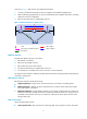
As shown in Figure 1, BFD sessions are established as follows: 1. A protocol sends Hello messages to discover neighbors and establish neighborships. 2. After establishing neighborships, the protocol notifies BFD of the neighbor information, including destination and source addresses. 3. BFD uses the information to establish BFD sessions.
• Echo packet mode—One end of the link sends Echo packets to the other end, which then forwards the packets back to the originating end, monitoring link status in both directions. BFD operating modes Before a BFD session is established, BFD has two operating modes—active and passive. • Active mode—BFD actively sends BFD control packets regardless of whether any BFD control packet is received from the peer.
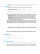
Figure 3 BFD packet format • Vers—Protocol version. The protocol version is 1. • Diag—This bit indicates the reason for the last transition of the local session from up to some other state. Table 4 lists the states. Table 4 Diag bit values Diag Description 0 No Diagnostic. 1 Control Detection Time Expired. 2 Echo Function Failed. 3 Neighbor Signaled Session Down. 4 Forwarding Plane Reset. 5 Path Down. 6 Concatenated Path Down. 7 Administratively Down. 8 Reverse Concatenated Path Down.
• Reserved (R)—This byte must be set to zero on transmit, and ignored on receipt. • Detect Mult—Detection time multiplier. • Length—Length of the BFD control packet, in bytes. • My Discriminator—A unique, nonzero discriminator value generated by the transmitting system, used to demultiplex multiple BFD sessions between the same pair of systems. • Your Discriminator—It is the discriminator received from the remote system.
RFC 5885, Bidirectional Forwarding Detection (BFD) for the Pseudowire Virtual Circuit Connectivity Verification (VCCV) • Configuring BFD basic functions The BFD basic function configuration is the basis for configuring BFD for other protocols. Configuration prerequisites Before configuring BFD basic functions, complete the following tasks: • Configure the network layer addresses of the interfaces so that adjacent nodes are reachable to each other at the network layer.
Step Command Remarks Optional. Configure the minimum interval for receiving BFD control packets. 8. bfd min-receive-interval value For more information, see the description of the Required Min RX Interval field in "BFD packet format." Optional. Configure the detection time multiplier. 9. bfd detect-multiplier value For more information, see the description of the Detect Mult field in "BFD packet format." 5 by default. 10. Configure the authentication mode on the interface.
Step Command Remarks Optional. Enabled by default. 12. Enable BFD trap. snmp-agent trap enable bfd For more information about the command, see the snmp-agent trap enable command in Network Management and Monitoring Command Reference. Displaying and maintaining BFD Task Command Remarks Display information about BFD-enabled interfaces. display bfd interface [ verbose ] [ | { begin | exclude | include } regular-expression ] Available in any view. Display information about enabled BFD debugging.
Configuring interface backup Overview Interface backup increases network reliability. The active interface transmits services, and the standby interfaces are in the backup state. When the active interface fails or the link fails, or when the traffic on the active interface exceeds the configured threshold, a standby interface is activated to transmit services. As shown in Figure 4, interfaces Serial 2/0, Serial 2/1, and Serial 2/2 on Router A back up each other.
How interface backup works Interface backup operates in active/standby mode or in load balancing mode. Active/standby mode As shown in Figure 5, interface Serial 2/0 on Router A acts as the active interface and interfaces Serial 2/1 and Serial 2/2 act as the standby interfaces. Figure 5 Diagram for active/standby mode In active/standby mode, only one interface transmits data at any given time.
NOTE: Adopt active/standby or load balancing mode depending on whether you have configured an upper or lower threshold for the active interface traffic. If this threshold is configured, load balancing mode is adopted. Otherwise, active/standby mode is adopted.
Step Command 4. standby timer delay enable-delay disable-delay Set switchover delays. Remarks Optional. Both thresholds are 0 by default, indicating immediate switchover without delay. Associating an interface with a track entry You can associate a standby interface with a track entry to enable the interface to monitor the state of the active interface through the track entry and change the backup state of the interface accordingly.
IMPORTANT: When you use the load balancing function, use the undo ip fast-forwarding command to disable fast forwarding on both the active interface and the standby interfaces. For more information about the undo ip fast-forwarding command, see Layer 3—IP Services Command Reference. To configure load balancing: Step Command Remarks 1. Enter system view. system-view N/A 2. Enter active interface view. interface interface-type interface-number N/A 3.
Displaying and maintaining interface backup Task Command Remarks Display statistics about the traffic on the active interfaces enabled with load balancing. display standby flow [ | { begin | exclude | include } regular-expression ] Available in any view. Display the state information of the active and standby interfaces. display standby state [ | { begin | exclude | include } regular-expression ] Available in any view.
3. Configure the standby interfaces and switch delays on Router A: # Specify interfaces Serial 2/1 and Serial 2/2 on Router A to back up Serial 2/0, and assign them the priorities 30 and 20, respectively. [RouterA] interface serial 2/0 [RouterA-Serial2/0] standby interface serial 2/1 30 [RouterA-Serial2/0] standby interface serial 2/2 20 # Configure switchover delays to 10 seconds. [RouterA-Serial2/0] standby timer delay 10 10 4.
Figure 8 Network diagram Configuration procedure 1. Configure IP addresses: Follow Figure 8 to configure the IP address and subnet mask for each interface. (Details not shown.) 2. Configure a static route: # On Router A, configure a static route to the segment 192.168.2.0/24 where Host B resides. system-view [RouterA] ip route-static 192.168.2.0 24 serial 2/0 [RouterA] ip route-static 192.168.2.0 24 serial 2/1 [RouterA] ip route-static 192.168.2.
[RouterB-Serial2/1] undo ip fast-forwarding [RouterB-Serial2/1] quit [RouterB] interface serial 2/2 [RouterB-Serial2/2] undo ip fast-forwarding [RouterB-Serial2/2] quit 4. Configure the standby interfaces and load balancing on Router A: # Specify interfaces Serial 2/1 and Serial 2/2 on Router A to back up Serial 2/0, and assign them the priorities 30 and 20, respectively.
D---LOAD P---PULLED 21
Configuring Track Track overview The Track module works between application and detection modules, as shown in Figure 9. It shields the differences between various detection modules from application modules. Collaboration is enabled after you associate the Track module with a detection module and an application module. The detection module probes specific objects such as interface status, link status, network reachability, and network performance, and informs the Track module of detection results.
• BFD. • Interface management module. Collaboration between the Track module and an application module After being associated with an application module, when the status of the track entry changes, the Track module notifies the application module, which then takes proper actions. The following application modules can be associated with the Track module: • VRRP. • Static routing. • Policy-based routing. • Interface backup.
If the uplink fails, the AC disables the radio on the AP that associates with the AC. If the uplink recovers, the AC enables the radio on the AP. For this purpose, configure collaboration between the NQA, Track, and uplink detection: 1. Configure an NQA test group to check the accessibility of the Device. 2. Create a track entry and associate it with the NQA test group. When the Device is reachable, the track entry is in Positive state.
To associate Track with NQA: Step Command Remarks 1. Enter system view. system-view N/A 2. Create a track entry, associate it with an NQA reaction entry, and specify the delay time for the Track module to notify the associated application module when the track entry status changes. track track-entry-number nqa entry admin-name operation-tag reaction item-number [ delay { negative negative-time | positive positive-time } *] No track entry is created by default.
Associating Track with interface management The interface management module monitors the physical status or network-layer protocol status of the interface. The interface management module functions as follows when it is associated with a track entry: • When the physical or network-layer protocol status of the interface changes to up, the interface management module informs the Track module of the change and the Track module sets the track entry to Positive.
gateway to undertake the responsibility of the failed master. This ensures that the hosts in the network segment can uninterruptedly communicate with external networks. When VRRP is operating in standard protocol mode or load balancing mode, associate the Track module with the VRRP group to implement the following actions: • Change the priority of a router according to the status of the uplink. If a fault occurs on the uplink of the router, the VRRP group cannot be aware of the uplink failure.
To associate Track with VRRP VF: Step Command Remarks 1. Enter system view. system-view N/A 2. Enter interface view. interface interface-type interface-number N/A 3. Create a VRRP group and configure its virtual IP address. vrrp vrid virtual-router-id virtual-ip virtual-address No VRRP group is created by default. • Associate a track entry with the VRRP VF: vrrp [ ipv6 ] vrid virtual-router-id weight track track-entry-number [ reduced weight-reduced ] 4. Associate Track with VRRP VF.
• If the Track module detects the next hop accessibility of the static route in a private network through NQA, the VPN instance name of the next hop of the static route must be consistent with that configured for the NQA test group. Otherwise, accessibility detection cannot function correctly. • If a static route needs route recursion, the associated track entry must monitor the next hop of the recursive route instead of that of the static route. Otherwise, a valid route might be considered invalid.
• The Negative state of the track entry shows that the object is not available, and the apply clause is invalid. • The Invalid state of the track entry shows that the apply clause is valid. The following objects can be associated with a track entry: • Outgoing interface. • Next hop. • Default outgoing interface. • Default next hop. Configuration prerequisites Before you associate Track with PBR, create a policy or a policy node and configure the match criteria as well.
Step Command Remarks • Set the outgoing interface, and associate it with a track entry: apply output-interface interface-type interface-number [ track track-entry-number ] [ interface-type interface-number [ track track-entry-number ] ] • Set the next hop, and associate it with a Associate Track with PBR. 4.
Step Command Remarks 2. Enter interface view. interface interface-type interface-number N/A 3. Associate the interface with a track entry. standby track track-entry-number Not configured by default. NOTE: You can associate an interface with only one track entry. If you execute the standby track command repeatedly, the last configuration takes effect. Displaying and maintaining track entries Task Command Remarks Display information about the specified or all track entries.
Figure 11 Network diagram Configuration procedure 1. Configure the IP address of each interface as shown in Figure 11. (Details not shown.) 2. Configure an NQA test group on Router A: # Create an NQA test group with the administrator name admin and the operation tag test. system-view [RouterA] nqa entry admin test # Configure the test type as ICMP echo test. [RouterA-nqa-admin-test] type icmp-echo # Configure the destination address as 10.1.2.2.
[RouterA-Ethernet1/1] vrrp vrid 1 authentication-mode simple hello # Configure the master to send VRRP packets at an interval of five seconds. [RouterA-Ethernet1/1] vrrp vrid 1 timer advertise 5 # Configure Router A to operate in preemptive mode, and set the preemption delay to five seconds. [RouterA-Ethernet1/1] vrrp vrid 1 preempt-mode timer delay 5 # Configure to monitor track entry 1 and specify the priority decrement to 30. [RouterA-Ethernet1/1] vrrp vrid 1 track 1 reduced 30 5.
Total number of virtual routers : 1 Interface Ethernet1/1 VRID : 1 Adver Timer : 5 Admin Status : Up State : Backup Config Pri : 100 Running Pri : 100 Preempt Mode : Yes Delay Time : 5 Become Master : 2200ms left Auth Type : Simple Key : ****** Virtual IP : 10.1.1.10 Master IP : 10.1.1.1 The output shows that in VRRP group 1, Router A is the master and Router B is a backup. Packets from Host A to Host B are forwarded through Router A.
Master IP : 10.1.1.2 The output shows that when a fault is on the link between Router A and Router C, the priority of Router A decreases to 80. Router A becomes the backup, and Router B becomes the master. Packets from Host A to Host B are forwarded through Router B. Configuring BFD for a VRRP backup to monitor the master Network requirements As shown in Figure 12, Router A and Router B belong to VRRP group 1, whose virtual IP address is 192.168.0.10. The default gateway of the hosts in the LAN is 192.
[RouterA-Ethernet1/1] vrrp vrid 1 virtual-ip 192.168.0.10 [RouterA-Ethernet1/1] vrrp vrid 1 priority 110 [RouterA-Ethernet1/1] return 2. Configure BFD on Router B: # Configure the source address of BFD echo packets as 10.10.10.10. system-view [RouterB] bfd echo-source-ip 10.10.10.10 3. Create a track entry to be associated with the BFD session on Router B: # Create track entry 1 to be associated with the BFD session to check whether Router A is reachable.
Preempt Mode : Yes Become Master : 2200ms left Auth Type : None Virtual IP : 192.168.0.10 Master IP : 192.168.0.101 Delay Time : 0 VRRP Track Information: Track Object : 1 State : Positive Switchover # Display information about track entry 1 on Router B.
Track Object : 1 State : Negative Switchover The output shows that when BFD detects that Router A fails, it notifies VRRP through the Track module to change the status of Router B to master without waiting for a period three times the advertisement interval. This ensures that a backup can quickly preempt as the master. Configuring BFD for the VRRP master to monitor the uplink Network requirements As shown in Figure 13, Router A and Router B belong to VRRP group 1, whose virtual IP address is 192.168.0.
3. Configure VRRP on Router A: # Create VRRP group 1, and configure the virtual IP address of the group as 192.168.0.10. Configure the priority of Router A in VRRP group 1 as 110, and configure VRRP group 1 to monitor the status of track entry 1. When the status of the track entry becomes Negative, the priority of Router A decreases by 20. [RouterA] interface ethernet 1/2 [RouterA-Ethernet1/2] vrrp vrid 1 virtual-ip 192.168.0.
# Display detailed information about the VRRP group on Router B. display vrrp verbose IPv4 Standby Information: Run Mode : Standard Run Method : Virtual MAC Total number of virtual routers : 1 Interface Ethernet1/2 VRID : 1 Adver Timer : 1 Admin Status : Up State : Backup Config Pri : 100 Running Pri : 100 Preempt Mode : Yes Delay Time : 0 Become Master : 2200ms left Auth Type : None Virtual IP : 192.168.0.10 Master IP : 192.168.0.
IPv4 Standby Information: Run Mode : Standard Run Method : Virtual MAC Total number of virtual routers : 1 Interface Ethernet1/2 VRID : 1 Adver Timer : 1 Admin Status : Up State : Master Config Pri : 100 Running Pri : 100 Preempt Mode : Yes Delay Time : 0 Auth Type : None Virtual IP : 192.168.0.10 Virtual MAC : 0000-5e00-0101 Master IP : 192.168.0.
Figure 14 Network diagram Configuration procedure 1. Configure the IP address of each interface as shown in Figure 14. (Details not shown.) 2. Configure Router A: # Configure a static route to 30.1.1.0/24, with the address of the next hop as 10.1.1.2 and the default priority 60. This static route is associated with track entry 1. system-view [RouterA] ip route-static 30.1.1.0 24 10.1.1.2 track 1 # Configure a static route to 30.1.1.0/24, with the address of the next hop as 10.3.1.
[RouterA] nqa schedule admin test start-time now lifetime forever # Configure track entry 1, and associate it with reaction entry 1 of the NQA test group (with the administrator admin, and the operation tag test). [RouterA] track 1 nqa entry admin test reaction 1 3. Configure Router B: # Configure a static route to 30.1.1.0/24, with the address of the next hop as 10.2.1.4. system-view [RouterB] ip route-static 30.1.1.0 24 10.2.1.4 # Configure a static route to 20.1.1.
[RouterD] track 1 nqa entry admin test reaction 1 Verifying the configuration # Display information about the track entry on Router A. [RouterA] display track all Track ID: 1 Status: Positive Duration: 0 days 0 hours 0 minutes 32 seconds Notification delay: Positive 0, Negative 0 (in seconds) Reference object: NQA entry: admin test Reaction: 1 # Display the routing table of Router A. [RouterA] display ip routing-table Routing Tables: Public Destinations : 10 Destination/Mask Proto 10.1.1.0/24 10.1.1.
Destinations : 10 Destination/Mask Proto 10.1.1.0/24 10.1.1.1/32 Routes : 10 Pre Cost NextHop Interface Direct 0 0 10.1.1.1 Eth1/1 Direct 0 0 127.0.0.1 InLoop0 10.2.1.0/24 Static 60 0 10.1.1.2 Eth1/1 10.3.1.0/24 Direct 0 0 10.3.1.1 Eth1/2 10.3.1.1/32 Direct 0 0 127.0.0.1 InLoop0 20.1.1.0/24 Direct 0 0 20.1.1.1 Eth1/3 20.1.1.1/32 Direct 0 0 127.0.0.1 InLoop0 30.1.1.0/24 Static 80 0 10.3.1.3 Eth1/2 127.0.0.0/8 Direct 0 0 127.0.0.1 InLoop0 127.0.0.
Static routing-Track-BFD collaboration configuration example Network requirements As shown in Figure 15, Router A, Router B, and Router C are connected to two segments 20.1.1.0/24 and 30.1.1.0/24. Configure static routes on these routers so that the two segments can communicate with each other. Configure route backup to improve network reliability. Router A is the default gateway of the hosts in segment 20.1.1.0/24. Two static routes to 30.1.1.
[RouterA] ip route-static 30.1.1.0 24 10.3.1.3 preference 80 # Configure the source address of BFD echo packets as 10.10.10.10. [RouterA] bfd echo-source-ip 10.10.10.10 # Configure track entry 1, and associate it with the BFD session. Check whether Router A can be interoperated with the next hop of static route, which is Router B. [RouterA] track 1 bfd echo interface ethernet 1/1 remote ip 10.2.1.2 local ip 10.2.1.1 3. Configure Router B: # Configure a static route to 20.1.1.
10.2.1.0/24 Direct 0 0 10.2.1.1 Eth1/1 10.2.1.1/32 Direct 0 0 127.0.0.1 InLoop0 10.3.1.0/24 Direct 0 0 10.3.1.1 Eth1/2 10.3.1.1/32 Direct 0 0 127.0.0.1 InLoop0 20.1.1.0/24 Direct 0 0 20.1.1.1 Eth1/3 20.1.1.1/32 Direct 0 0 127.0.0.1 InLoop0 30.1.1.0/24 Static 60 0 10.2.1.2 Eth1/1 127.0.0.0/8 Direct 0 0 127.0.0.1 InLoop0 127.0.0.1/32 Direct 0 0 127.0.0.1 InLoop0 The output shows the BFD detection result: the next hop 10.2.1.
# When the master route fails, the hosts in 20.1.1.0/24 can still communicate with the hosts in 30.1.1.0/24. [RouterA] ping -a 20.1.1.1 30.1.1.1 PING 30.1.1.1: 56 data bytes, press CTRL_C to break Reply from 30.1.1.1: bytes=56 Sequence=1 ttl=254 time=2 ms Reply from 30.1.1.1: bytes=56 Sequence=2 ttl=254 time=1 ms Reply from 30.1.1.1: bytes=56 Sequence=3 ttl=254 time=1 ms Reply from 30.1.1.1: bytes=56 Sequence=4 ttl=254 time=2 ms Reply from 30.1.1.1: bytes=56 Sequence=5 ttl=254 time=1 ms --- 30.1.1.
Figure 16 Network diagram Configuration procedure 1. Configure the IP address of each interface as shown in Figure 16. (Details not shown.) 2. Configure a track entry on Router A: # Configure track entry 1, and associate it with the physical status of the uplink interface Ethernet 1/2. [RouterA] track 1 interface ethernet 1/2 3. Configure VRRP on Router A: # Create VRRP group 1, and configure the virtual IP address 10.1.1.10 for the group.
VRID : 1 Adver Timer : 1 Admin Status : Up State : Master Config Pri : 110 Running Pri : 110 Preempt Mode : Yes Delay Time : 0 Auth Type : None Virtual IP : 10.1.1.10 Virtual MAC : 0000-5e00-0101 Master IP : 10.1.1.1 VRRP Track Information: Track Object : 1 State : Positive Pri Reduced : 30 # Display detailed information about VRRP group 1 on Router B.
Master IP : 10.1.1.2 VRRP Track Information: Track Object : 1 State : Negative Pri Reduced : 30 # After shutting down the uplink interface on Router A, display detailed information about VRRP group 1 on Router B.
Configuring VRRP The interfaces that VRRP involves can be only Layer 3 Ethernet interfaces and VLAN interfaces unless otherwise specified. VRRP overview As shown in Figure 17, you can typically configure a default route with the gateway as the next hop for every host on a LAN. All packets destined to other network segments are sent over the default route to the gateway, which then forwards the packets.
VRRP standard mode VRRP group VRRP combines a group of routers (including a master and multiple backups) on a LAN into a virtual router called VRRP group. A VRRP group has the following features: • A virtual router has a virtual IP address. A host on the LAN only needs to know the IP address of the virtual router and uses the IP address as the next hop of the default route. • Every host on the LAN communicates with external networks through the virtual router.
2. Working mode A router in a VRRP group operates in either of the following modes: { { 3. Non-preemptive mode—When a router in the VRRP group becomes the master, it stays as the master as long as it operates correctly, even if a backup is assigned a higher priority later. Preemptive mode—When a backup finds its priority higher than that of the master, the backup sends VRRP advertisements to start a new master election in the VRRP group and becomes the master.
Figure 19 IPv4 VRRPv2 packet format Figure 20 IPv6 VRRPv2 packet format 0 3 Version Auth Type 7 Type 15 23 Virtual Rtr ID Priority Adver Int 31 Count IPv6 Addrs Checksum IPv6 address 1 ...
• Version—Version number of the protocol, 2 for IPv4 VRRPv2, and 3 for IPv6 VRRPv2 and IPv4/IPv6 VRRPv3. • Type—Type of the VRRP packet. It must be VRRP advertisement, represented by 1. • Virtual Rtr ID (VRID)—ID of the virtual router. It ranges from 1 to 255. • Priority—Priority of the router in the VRRP group, in the range 0 to 255. A greater value represents a higher priority. • Count IP Addrs/Count IPv6 Addrs—Number of virtual IPv4 or IPv6 addresses for the VRRP group.
The interface tracking function expands the backup functionality of VRRP. It provides backup not only when the interface to which a VRRP group is assigned fails, but also when other interfaces (such as uplink interfaces) on the router become unavailable. If the uplink interface of a router in a VRRP group fails, usually the VRRP group cannot be aware of the uplink interface failure.
More than one VRRP group can be created on an interface of a router to allow the router to be the master of one VRRP group but a backup of another at the same time. In load sharing mode, multiple routers provide services simultaneously. This mode requires two or more VRRP groups, each of which comprises a master and one or more backups. The masters of the VRRP groups are assumed by different routers.
Virtual MAC address assignment In a load balanced VRRP group, the master assigns virtual MAC addresses to the member routers and answers the ARP requests or ND requests from different hosts. The backup routers do not answer the ARP requests or ND requests from the hosts. In an IPv4 network, a load-balanced VRRP group works as follows: 1. The master assigns virtual MAC addresses to all members, including itself. This example assumes that the virtual IP address of the VRRP group is 10.1.1.
Figure 25 Answering ARP requests Network Router A Master Router B Backup Virtual IP: 10.1.1.1/24 Virtual MAC: 000f-e2ff-0012 Virtual MAC: 000f-e2ff-0011 ARP request Target IP: 10.1.1.1/24 ARP reply Target MAC: 000f-e2ff-0011 ARP request Target IP: 10.1.1.1/24 ARP reply Target MAC: 000f-e2ff-0012 Gateway IP: 10.1.1.1/24 Gateway IP: 10.1.1.1/24 Host A 3. Host B Each host sends packets to the returned MAC address.
a. The master assigns virtual MAC addresses to all routers in the VRRP group. Each member router creates a VF for this MAC address and becomes the owner of this VF. b. Each router advertises its VF information to the other member routers. c. After receiving the VF advertisement, each of the other routers creates the advertised VF. Eventually, every member router maintains one VF for each virtual MAC address in the VRRP group. 2.
and 000f-e2ff-0013 to itself, Router B, and Router C, and each router creates VF 1, VF 2, and VF 3 for the virtual MAC addresses, respectively. The VFs for the same virtual MAC address on different routers back up one another. For example, the VF 1 instances on Router A, Router B, and Router C back up one another. { { { The VF 1 instance on Router A (the VF 1 owner) has priority 255 and acts as the AVF to forward the packets sent to virtual MAC address 000f-e2ff-0011.
• Request—If a backup is not the VF owner, it sends a request to ask the master to assign a virtual MAC address. • Reply—When receiving a request, the master sends a reply to the backup router to assign a virtual MAC address. After receiving the reply, the backup router creates a VF for the virtual MAC address, and becomes the owner of this VF.
Step Enter system view. 1. Command Remarks system-view N/A • Configure VRRP to operate in standard mode: undo vrrp mode Configure the VRRP operating mode. 2. • Configure VRRP to operate in load balancing mode: vrrp mode load-balance Use either command. By default, VRRP operates in standard mode. Specifying the IPv4 VRRP version This configuration does not apply to VRRP load balancing mode. The VRRP version on all routers in a VRRP group must be the same.
To specify the type of MAC addresses mapped to virtual IP addresses: Step Command Remarks 1. Enter system view. system-view N/A 2. Specify the type of MAC addresses mapped to virtual IP addresses. vrrp method { real-mac | virtual-mac } Optional. Virtual MAC address by default.
Configuration procedure To create a VRRP group and configure a virtual IP address: Step Command Remarks 1. Enter system view. system-view N/A 2. Enter the specified interface view. interface interface-type interface-number N/A 3. Create a VRRP group and configure a virtual IP address for the VRRP group. vrrp vrid virtual-router-id virtual-ip virtual-address VRRP group is not created by default.
Step Command Remarks 1. Enter system view. system-view N/A 2. Enter interface view. interface interface-type interface-number N/A 3. Configure router priority in the VRRP group. vrrp vrid virtual-router-id priority priority-value Optional. The default is 100. Optional. 4. Configure the router in the VRRP group to operate in preemptive mode and configure preemption delay.
Step Command Remarks 1. Enter system view. system-view N/A 2. Enter the specified interface view. interface interface-type interface-number N/A • Configure the VF tracking function to monitor a specified track entry and specify the value by which the weight decreases: vrrp vrid virtual-router-id weight track track-entry-number [ reduced weight-reduced ] Configure VF tracking. 3.
Step 3. 4. Command Remarks Configure the authentication mode and authentication key when the VRRP groups send and receive VRRP packets. vrrp vrid virtual-router-id authentication-mode { md5 | simple [ cipher ] } key Optional. Configure the time interval for the master in the VRRP group to send VRRP advertisements. vrrp vrid virtual-router-id timer advertise adver-interval Optional. Authentication is not performed by default. 1 second by default. Optional. 5. Disable TTL check on VRRP packets.
Task Command Remarks Clear VRRP group statistics. reset vrrp statistics [ interface interface-type interface-number [ vrid virtual-router-id ] ] Available in user view. Configuring IPv6 VRRP Task Remarks Specifying an IPv4 VRRP operating mode Optional. Specifying the IPv4 VRRP version Optional. Specifying the type of MAC addresses mapped to virtual IPv6 addresses Optional. When VRRP operates in load balancing mode, this configuration is not effective.
Specify the type of the MAC addresses mapped to the virtual IPv6 addresses before creating a VRRP group. Otherwise, you cannot change the type of the MAC addresses mapped to virtual IPv6 addresses. To specify the type of MAC addresses mapped to virtual IPv6 addresses: Step Command Remarks 1. Enter system view. system-view N/A 2. Specify the type of MAC addresses mapped to virtual IPv6 addresses. vrrp ipv6 method { real-mac | virtual-mac } Optional. Virtual MAC address by default.
Step 2. Enter the specified interface view. Command Remarks interface interface-type interface-number N/A No VRRP group is created by default. 3. 4. Create a VRRP group and configure its virtual IPv6 address, which is a link local address. Configure the VRRP group with a virtual IPv6 address, which is a global unicast address. vrrp ipv6 vrid virtual-router-id virtual-ip virtual-address link-local The first virtual IPv6 address of the VRRP group must be a link local address.
Step Command Remarks 1. Enter system view. system-view N/A 2. Enter the specified interface view. interface interface-type interface-number N/A 3. Configure the priority of the router in the VRRP group. vrrp ipv6 vrid virtual-router-id priority priority-value Optional. 100 by default. Optional. Configure the router in the VRRP group to operate in preemptive mode and configure preemption delay of the VRRP group.
Step Command Remarks 1. Enter system view. system-view N/A 2. Enter the specified interface view. interface interface-type interface-number N/A • Configure the VF tracking function to monitor a specified track entry and specify the value by which the weight decreases: vrrp ipv6 vrid virtual-router-id weight track track-entry-number [ reduced weight-reduced ] Configure VF tracking. 3.
Step 3. 4. Command Remarks Configure the authentication mode and authentication key when the VRRP groups send or receive VRRP packets. vrrp ipv6 vrid virtual-router-id authentication-mode simple [ cipher ] key Optional. Configure the time interval for the master in the VRRP group to send VRRP advertisement. vrrp ipv6 vrid virtual-router-id timer advertise adver-interval Optional. Authentication is not performed by default. 100 centiseconds by default.
Figure 28 Network diagram Configuration procedure 1. Configure Router A: system-view [RouterA] interface ethernet 1/1 [RouterA-Ethernet1/1] ip address 202.38.160.1 255.255.255.0 # Create VRRP group 1 and configure its virtual IP address as 202.38.160.111. [RouterA-Ethernet1/1] vrrp vrid 1 virtual-ip 202.38.160.111 # Configure the priority of Router A in the VRRP group 1 as 110, which is higher than that of Router B (100), so that Router A can become the master.
Total number of virtual routers : 1 Interface Ethernet1/1 VRID : 1 Adver Timer : 1 Admin Status : Up State : Master Config Pri : 110 Running Pri : 110 Preempt Mode : Yes Delay Time : 5 Auth Type : None Virtual IP : 202.38.160.111 Virtual MAC : 0000-5e00-0101 Master IP : 202.38.160.1 # Display the detailed information about VRRP group 1 on Router B.
# After Router A resumes normal operation, use the display vrrp verbose command to display the detailed information about VRRP group 1 on Router A. [RouterA-Ethernet1/1] display vrrp verbose IPv4 Standby Information: Run Mode : Standard Run Method : Virtual MAC Total number of virtual routers : 1 Interface Ethernet1/1 VRID : 1 Adver Timer : 1 Admin Status : Up State : Master Config Pri : 110 Running Pri : 110 Preempt Mode : Yes Delay Time : 5 Auth Type : None Virtual IP : 202.38.160.
Configuration procedure 1. Configure Router A: system-view [RouterA] interface ethernet 1/2 [RouterA-Ethernet1/2] ip address 202.38.160.1 255.255.255.0 # Create VRRP group 1 and configure its virtual IP address as 202.38.160.111. [RouterA-Ethernet1/2] vrrp vrid 1 virtual-ip 202.38.160.111 # Configure the priority of Router A in the VRRP group as 110, which is higher than that of Router B (100), so that Router A can become the master.
Total number of virtual routers : 1 Interface Ethernet1/2 VRID : 1 Adver Timer : 4 Admin Status : Up State : Master Config Pri : 110 Running Pri : 110 Preempt Mode : Yes Delay Time : 5 Auth Type : Simple Key : hello Virtual IP : 202.38.160.111 Virtual MAC : 0000-5e00-0101 Master IP : 202.38.160.1 VRRP Track Information: Track Interface: Eth1/1 State : Up Pri Reduced : 30 # Display the detailed information about VRRP group 1 on Router B.
VRRP Track Information: Track Interface: Eth1/1 State : Down Pri Reduced : 30 # If interface Ethernet 1/1 on Router A is not available, the detailed information about VRRP group 1 on Router B is displayed.
Configuration procedure 1. Configure Router A: system-view [RouterA] interface ethernet 1/1 [RouterA-Ethernet1/1] ip address 202.38.160.1 255.255.255.0 # Create VRRP group 1 and configure its virtual IP address as 202.38.160.111. [RouterA-Ethernet1/1] vrrp vrid 1 virtual-ip 202.38.160.111 # Set the priority of Router A in VRRP group 1 to 110, which is higher than that of Router B (100), so that Router A can become the master in VRRP group 1.
Auth Type : None Virtual IP : 202.38.160.112 Master IP : 202.38.160.2 # Display the detailed information about the VRRP group on Router B.
• Configure track entries on Router C to monitor Router A and Router B. When Router A or Router B fails, Router C immediately takes over the AVF on Router A or Router B. Figure 31 Network diagram Network Router A Router B Eth1/2 Eth1/2 Master AVF 1 Backup AVF 2 Eth1/1 IP: 10.1.1.2/24 VIP: 10.1.1.1/24 Eth1/1 IP: 10.1.1.3/24 VIP: 10.1.1.1/24 IP: 10.1.1.5/24 Gateway IP: 10.1.1.1/24 IP: 10.1.1.6/24 Gateway IP: 10.1.1.1/24 Host A Router C Eth1/2 Backup AVF 3 Eth1/1 IP: 10.1.1.4/24 VIP: 10.1.1.
# Configure VF tracking to monitor track entry 1 and specify the value by which the weight decreases, making the weight of Router A decrease by more than 245 (250 in this example) when track entry 1 turns to negative. In such a case, another router with a higher weight can take over. [RouterA] interface ethernet 1/1 [RouterA-Ethernet1/1] vrrp vrid 1 weight track 1 reduced 250 2. Configure Router B: # Configure VRRP to operate in load balancing mode.
[RouterC-Ethernet1/1] quit # Create track entries 2 and 3 to monitor Router A and Router B, respectively. If a track entry becomes negative, it indicates that the corresponding router fails. [RouterC] bfd echo-source-ip 1.2.3.4 [RouterC] track 2 bfd echo interface ethernet 1/1 remote ip 10.1.1.2 local ip 10.1.1.4 [RouterC] track 3 bfd echo interface ethernet 1/1 remote ip 10.1.1.3 local ip 10.1.1.4 # Configure VF tracking to monitor track entry 2.
Owner ID : 0000-5e01-1103 Priority : 127 Active : 10.1.1.3 Forwarder 03 State : Listening Virtual MAC : 000f-e2ff-0013 (Learnt) Owner ID : 0000-5e01-1105 Priority : 127 Active : 10.1.1.4 Forwarder Weight Track Information: Track Object : 1 State : Positive # Display the detailed information about VRRP group 1 on Router B.
Active : 10.1.1.4 Forwarder Weight Track Information: Track Object : 1 State : Positive Weight Reduced : 250 # Display the detailed information about VRRP group 1 on Router C.
The output shows that in VRRP group 1, Router A is the master and Router B and Router C are the backups. Each router has one AVF and two LVFs that act as the backups. # When Ethernet 1/2 on Router A fails, use the display vrrp verbose command to display the detailed information about VRRP group 1 on Router A.
Total number of virtual routers : 1 Interface Ethernet1/1 VRID : 1 Adver Timer : 1 Admin Status : Up State : Backup Config Pri : 100 Running Pri : 100 Preempt Mode : Yes Delay Time : 5 Become Master : 4200ms left Auth Type : None Virtual IP : 10.1.1.1 Member IP List : 10.1.1.4 (Local, Backup) 10.1.1.2 (Master) 10.1.1.
# When the timeout timer (about 1800 seconds) expires, display the detailed information about VRRP group 1 on Router C. [RouterC-Ethernet1/1] display vrrp verbose IPv4 Standby Information: Run Mode : Load Balance Run Method : Virtual MAC Total number of virtual routers : 1 Interface Ethernet1/1 VRID : 1 Adver Timer : 1 Admin Status : Up State : Backup Config Pri : 100 Running Pri : 100 Preempt Mode : Yes Delay Time : 5 Become Master : 4200ms left Auth Type : None Virtual IP : 10.1.
Run Method : Virtual MAC Total number of virtual routers : 1 Interface Ethernet1/1 VRID : 1 Adver Timer : 1 Admin Status : Up State : Master Config Pri : 110 Running Pri : 110 Preempt Mode : Yes Delay Time : 5 Auth Type : None Virtual IP : 10.1.1.1 Member IP List : 10.1.1.3 (Local, Master) 10.1.1.
Forwarder 02 State : Active Virtual MAC : 000f-e2ff-0012 (Take Over) Owner ID : 0000-5e01-1103 Priority : 85 Active : local Redirect Time : 93 secs Time-out Time : 1293 secs Forwarder 03 State : Active Virtual MAC : 000f-e2ff-0013 (Owner) Owner ID : 0000-5e01-1105 Priority : 255 Active : local Forwarder Weight Track Information: Track Object : 1 State : Positive Weight Reduced : 250 Forwarder Switchover Track Information: Track Object Member IP Track Object Member IP : 2 State
Figure 32 Network diagram Configuration procedure 1. Configure Router A: system-view [RouterA] ipv6 [RouterA] interface ethernet 1/1 [RouterA-Ethernet1/1] ipv6 address fe80::1 link-local [RouterA-Ethernet1/1] ipv6 address 1::1 64 # Create a VRRP group 1 and set its virtual IPv6 addresses to FE80::10 and 1::10.
# Enable Router B to send RA messages, so that Host A can learns the default gateway address. [RouterB-Ethernet1/1] undo ipv6 nd ra halt 3. Verify the configuration: After the configuration, Host B can be pinged successfully on Host A. To verify your configuration, use the display vrrp ipv6 verbose command. # Display the detailed information about VRRP group 1 on Router A.
Interface Ethernet1/1 VRID : 1 Adver Timer : 100 Admin Status : Up State : Master Config Pri : 100 Running Pri : 100 Preempt Mode : Yes Delay Time : 5 Auth Type : None Virtual IP : FE80::10 1::10 Virtual MAC : 0000-5e00-0201 Master IP : FE80::2 The output shows that when Router A fails, Router B becomes the master, and packets sent from Host A to Host B are forwarded by Router B.
Figure 33 Network diagram Configuration procedure 1. Configure Router A: system-view [RouterA] ipv6 [RouterA] interface ethernet 1/2 [RouterA-Ethernet1/2] ipv6 address fe80::1 link-local [RouterA-Ethernet1/2] ipv6 address 1::1 64 # Create a VRRP group 1 and set its virtual IPv6 addresses to FE80::10 and 1::10.
[RouterB] interface ethernet 1/2 [RouterB-Ethernet1/2] ipv6 address fe80::2 link-local [RouterB-Ethernet1/2] ipv6 address 1::2 64 # Create a VRRP group 1 and set its virtual IPv6 addresses to FE80::10 and 1::10. [RouterB-Ethernet1/2] vrrp ipv6 vrid 1 virtual-ip fe80::10 link-local [RouterB-Ethernet1/2] vrrp ipv6 vrid 1 virtual-ip 1::10 # Set the authentication mode of VRRP group 1 as simple and authentication key as hello.
Preempt Mode : Yes Become Master : 2200ms left Auth Type : Simple Virtual IP : FE80::10 Master IP : FE80::1 Delay Time : 5 Key : hello 1::10 The output shows that in VRRP group 1 Router A is the master, Router B is the backup and packets sent from Host A to Host B are forwarded by Router A. When interface Ethernet 1/1 on Router A is not available, you can still ping Host B on Host A. To view the detailed information about the VRRP group, use the display vrrp ipv6 verbose command.
The output shows that when interface Ethernet 1/1 on Router A is not available, the priority of Router A reduces to 80 and it becomes the backup. Router B becomes the master and packets sent from Host A to Host B are forwarded by Router B. Multiple VRRP groups configuration example Network requirements • In the network, some hosts use 1::10/64 as their default gateway and some hosts use 1::20/64 as their default gateway.
system-view [RouterB] ipv6 [RouterB] interface ethernet 1/1 [RouterB-Ethernet1/1] ipv6 address fe80::2 link-local [RouterB-Ethernet1/1] ipv6 address 1::2 64 # Create VRRP group 1 and set its virtual IPv6 addresses to FE80::10 and 1::10. [RouterB-Ethernet1/1] vrrp ipv6 vrid 1 virtual-ip fe80::10 link-local [RouterB-Ethernet1/1] vrrp ipv6 vrid 1 virtual-ip 1::10 # Create VRRP group 2 set its virtual IPv6 addresses to FE80::20 and 1::20.
Total number of virtual routers : 2 Interface Ethernet1/1 VRID : 1 Adver Timer : 100 Admin Status : Up State : Backup Config Pri : 100 Running Pri : 100 Preempt Mode : Yes Delay Time : 0 Become Master : 2200ms left Auth Type : None Virtual IP : FE80::10 1::10 Master IP : FE80::1 Interface Ethernet1/1 VRID : 2 Adver Timer : 100 Admin Status : Up State : Master Config Pri : 110 Running Pri : 110 Preempt Mode : Yes Delay Time : 0 Auth Type : None Virtual IP : FE80::20
Figure 35 Network diagram Configuration procedure 1. Configure Router A: # Configure VRRP to operate in load balancing mode. system-view [RouterA] vrrp mode load-balance # Create VRRP group 1 and configure its virtual IPv6 addresses as FE80::10 and 1::10.
[RouterA] track 1 interface ethernet 1/2 # Configure VF tracking to monitor track entry 1 and specify the value by which the weight decreases, making the weight of Router A decrease by more than 245 (250 in this example) when track entry 1 turns to negative. In such a case, another router with a higher weight can take over. [RouterA] interface ethernet 1/1 [RouterA-Ethernet1/1] vrrp ipv6 vrid 1 weight track 1 reduced 250 2. Configure Router B: # Configure VRRP to operate in load balancing mode.
# Enable Router C to send RA messages, so that hosts in network segment 1::/64 can learn the default gateway address. [RouterC-Ethernet1/1] undo ipv6 nd ra halt [RouterC-Ethernet1/1] quit # Create track entry 1 to associate with the physical status of Ethernet 1/2 on Router C. When the track entry becomes negative, it means that the interface fails.
State : Listening Virtual MAC : 000f-e2ff-4013 (Learnt) Owner ID : 0000-5e01-1105 Priority : 127 Active : FE80::3 Forwarder Weight Track Information: Track Object : 1 State : Positive Weight Reduced : 250 # Display the detailed information about VRRP group 1 on Router B.
# Display the detailed information about VRRP group 1 on Router C.
Run Method : Virtual MAC Total number of virtual routers : 1 Interface Ethernet1/1 VRID : 1 Adver Timer : 100 Admin Status : Up State : Master Config Pri : 120 Running Pri : 120 Preempt Mode : Yes Delay Time : 5 Auth Type : None Virtual IP : FE80::10 1::10 Member IP List : FE80::1 (Local, Master) FE80::2 (Backup) FE80::3 (Backup) Forwarder Information: 3 Forwarders 0 Active Config Weight : 255 Running Weight : 5 Forwarder 01 State : Initialize Virtual MAC : 000f-e2ff-4011 (Owner)
Become Master : 4200ms left Auth Type : None Virtual IP : FE80::10 1::10 Member IP List : FE80::3 (Local, Backup) FE80::1 (Master) FE80::2 (Backup) Forwarder Information: 3 Forwarders 2 Active Config Weight : 255 Running Weight : 255 Forwarder 01 State : Active Virtual MAC : 000f-e2ff-4011 (Take Over) Owner ID : 0000-5e01-1101 Priority : 85 Active : local Redirect Time : 93 secs Time-out Time : 1293 secs Forwarder 02 State : Listening Virtual MAC : 000f-e2ff-4012 (Learnt) Owner ID
Preempt Mode : Yes Become Master : 4200ms left Delay Time Auth Type : None Virtual IP : FE80::10 : 5 1::10 Member IP List : FE80::3 (Local, Backup) FE80::1 (Master) FE80::2 (Backup) Forwarder Information: 2 Forwarders 1 Active Config Weight : 255 Running Weight : 255 Forwarder 02 State : Listening Virtual MAC : 000f-e2ff-4012 (Learnt) Owner ID : 0000-5e01-1103 Priority : 127 Active : FE80::2 Forwarder 03 State : Active Virtual MAC : 000f-e2ff-4013 (Owner) Owner ID : 0000-5e01-1105
Forwarder 02 State : Active Virtual MAC : 000f-e2ff-4012 (Owner) Owner ID : 0000-5e01-1103 Priority : 255 Active : local Forwarder 03 State : Listening Virtual MAC : 000f-e2ff-4013 (Learnt) Owner ID : 0000-5e01-1105 Priority : 127 Active : FE80::3 Forwarder Weight Track Information: Track Object : 1 State : Positive Weight Reduced : 250 The output shows that when Router A fails, Router B becomes the master because its priority is higher than that of Router C.
• If the ping succeeds, check that their configurations are consistent in terms of number of virtual IP addresses, virtual IP addresses, advertisement interval, and authentication. Frequent VRRP state transition Symptom Frequent VRRP state transition. Analysis The VRRP advertisement interval is set too short. Solution Increase the interval for sending VRRP advertisements or configure a preemption delay.
Support and other resources Contacting HP For worldwide technical support information, see the HP support website: http://www.hp.
Conventions This section describes the conventions used in this documentation set. Command conventions Convention Description Boldface Bold text represents commands and keywords that you enter literally as shown. Italic Italic text represents arguments that you replace with actual values. [] Square brackets enclose syntax choices (keywords or arguments) that are optional. { x | y | ... } Braces enclose a set of required syntax choices separated by vertical bars, from which you select one.
Network topology icons Represents a generic network device, such as a router, switch, or firewall. Represents a routing-capable device, such as a router or Layer 3 switch. Represents a generic switch, such as a Layer 2 or Layer 3 switch, or a router that supports Layer 2 forwarding and other Layer 2 features. Represents an access controller, a unified wired-WLAN module, or the switching engine on a unified wired-WLAN switch. Represents an access point.
Index ACDEHIORTV A Enabling trap,10 Associating the Track module with a detection module,24 H High availability technologies,2 Associating the Track module with an application module,26 I Interface backup configuration examples,17 Availability evaluation,1 Interface backup configuration task list,14 Availability requirements,1 Introduction to BFD,4 C IPv4 VRRP configuration examples,77 Configuring BFD basic functions,9 IPv6 VRRP configuration examples,95 Configuring interface backup,14 O Con