
R2511-HP MSR Router Series High Availability Configuration Guide(V5)


104
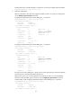
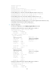
Total number of virtual routers : 2
Interface Ethernet1/1
VRID : 1 Adver Timer : 100
Admin Status : Up State : Backup
Config Pri : 100 Running Pri : 100
Preempt Mode : Yes Delay Time : 0
Become Master : 2200ms left
Auth Type : None
Virtual IP : FE80::10
1::10
Master IP : FE80::1
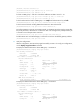
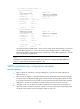
Interface Ethernet1/1
VRID : 2 Adver Timer : 100
Admin Status : Up State : Master
Config Pri : 110 Running Pri : 110
Preempt Mode : Yes Delay Time : 0
Auth Type : None
Virtual IP : FE80::20
1::20
Virtual MAC : 0000-5e00-0202
Master IP : FE80::2
The output shows that in VRRP group 1, Router A is the master, Router B is the backup, and the host
with the default gateway of 1::10/64 access the Internet through Router A. In VRRP group 2,
Router A is the backup, Router B is the master, and the host with the default gateway of 1::20/64
access the Internet through Router B.
NOTE:
To implement load balancing between the VRRP groups, be sure to confi
g
ure the default
g
ateway as
1::10 or 1::20 on the hosts on network segment 1::/64.
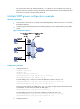
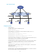
VRRP load balancing configuration example
Network requirements
• Router A, Router B, and Router C belong to VRRP group 1 with the virtual IPv6 addresses of
FE80::10 and 1::10.
• Hosts on network segment 1::/64 learn FE80::10 as their default gateway through RA messages
sent by the routers. Configure the VRRP group to make sure that when a gateway (Router A, Router
B, or Router C) fails, the hosts on the LAN can access external networks through another gateway.
• VRRP group 1 operates in load balancing mode to make good use of network resources.
• Configure a track entry on Router A, Router B, and Router C to monitor their own Ethernet 1/2.
When the interface on Router A, Router B, or Router C fails, the weight of the corresponding router
decreases so that another router with a higher weight can take over.