
R2511-HP MSR Router Series High Availability Configuration Guide(V5)

10
Ste
p
Command
Remarks
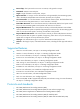
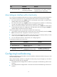
8. Configure the minimum
interval for receiving BFD
control packets.
bfd min-receive-interval value
Optional.
For more information, see the
description of the Required Min RX
Interval field in "BFD packet
format."
9. Configure the detection time
multiplier.
bfd detect-multiplier value
Optional.
For more information, see the
description of the Detect Mult field
in "BFD packet format."
5
by default.
10. Configure the authentication
mode on the interface.
bfd authentication-mode { md5
key-id [ cipher ] key | sha1 key-id
[ cipher ] key | simple key-id
[ cipher ] password }
Optional.
By default, the interface does not
authenticate BFD packets.
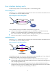
In Figure 1, if you configure the Desired Min TX Interval as 100 milliseconds, Required Min RX Interval as
300 milliseconds, and Detect Mult as 5 on Router A, and then configure the Desired Min TX Interval as
200 milliseconds, Required Min RX Interval as 400 milliseconds, and Detect Mult as 10 on Router B:
• The actual transmitting interval on Router A is 400 milliseconds, which is the greater value between
the minimum interval for transmitting BFD control packets on Router A (100 milliseconds) and the
minimum interval for receiving BFD control packets on Router B (400 milliseconds).
• The actual transmitting interval on Router B is 300 milliseconds, which is the greater value between
the minimum interval for transmitting BFD control packets on Router B (200 milliseconds) and the
minimum interval for receiving BFD control packets on Router A (300 milliseconds).
• The actual detection time on Router A is 3000 milliseconds, which is 10 × 300 milliseconds (Detect
Mult on Router B × actual transmitting interval on Router B).
• The actual detection time on Router B is 2000 milliseconds, which is 5 × 400 milliseconds (Detect
Mult on Router A × actual transmitting interval on Router A).
Enabling trap
When the trap function is enabled on the BFD module, the module will generate trap messages at the
notifications level to report the important events of the module. The generated trap messages are sent to
the device's information center, which determines the output rules for the trap messages (whether to
output the trap messages and the output destinations). For the information center configuration, see
Network Management and Monitoring Configuration Guide.
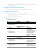
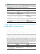
To enable BFD trap:
Ste
p
Command
Remarks
11. Enter system view.
system-view N/A