
R2511-HP MSR Router Series High Availability Configuration Guide(V5)


17
Displaying and maintaining interface backup
Task Command
Remarks
Display statistics about the traffic
on the active interfaces enabled
with load balancing.
display standby flow [ | { begin | exclude
| include } regular-expression ]
Available in any view.
Display the state information of the
active and standby interfaces.
display standby state [ | { begin | exclude
| include } regular-expression ]
Available in any view.
Interface backup configuration examples
Multi-interface backup configuration example
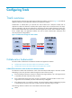
Network requirements
Use interfaces Serial 2/1 and Serial 2/2 on Router A to back up the active interface Serial 2/0,
assigning interface Serial 2/1 a higher priority, and configure switchover delays.
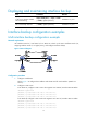
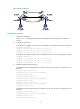
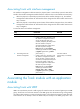
Figure 7 Network diagram
Configuration procedure
1. Configure IP addresses:
Follow Figure 7 to c
onfigure the IP address and subnet mask for each interface. (Details not
shown.)
2. Configure a static route:
# On Router A, configure a static route to the segment 192.168.2.0/24 where Host B resides.
<RouterA> system-view
[RouterA] ip route-static 192.168.2.0 24 serial 2/0
[RouterA] ip route-static 192.168.2.0 24 serial 2/1
[RouterA] ip route-static 192.168.2.0 24 serial 2/2
# On Router B, configure a static route to the segment 192.168.1.0/24 where Host A resides.
<RouterB> system-view
[RouterB] ip route-static 192.168.1.0 24 serial 2/0
[RouterB] ip route-static 192.168.1.0 24 serial 2/1
[RouterB] ip route-static 192.168.1.0 24 serial 2/2