
R2511-HP MSR Router Series High Availability Configuration Guide(V5)

5
As shown in Figure 1, BFD sessions are established as follows:
1. A protocol sends Hello messages to discover neighbors and establish neighborships.
2. After establishing neighborships, the protocol notifies BFD of the neighbor information, including
destination and source addresses.
3. BFD uses the information to establish BFD sessions.
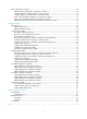
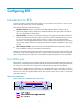
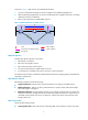
Figure 2 BFD fault detection (on OSPF routers)
BFD fault detection
The BFD fault detection process is as follows:
1. BFD detects a link failure.
2. BFD clears the neighbor session.
3. BFD notifies the protocol of the failure.
4. The protocol terminates the neighborship on the link.
5. If a backup link is available, the protocol will use it to forward packets.
No detection time resolution is defined in the BFD draft. Most devices supporting BFD provide detection
measured in milliseconds.
BFD detection methods
BFD detection methods include the following:
• Single-hop detection—Detects the IP connectivity between two directly connected systems.
• Multi-hop detection—Detects any of the paths between two systems. These paths have multiple
hops and might be overlapped.
• Bidirectional detection—Sends detection packets at two sides of a bidirectional link to detect the
bidirectional link status, finding link failures in milliseconds. (BFD LSP detection is a special case, in
which BFD control packets are sent in one direction, and the peer device reports the link status
through other links.)
BFD session modes
Session modes for BFD include:
• Control packet mode—Both ends of the link exchange BFD control packets to monitor link status.
5
OSPF neighbors
BFD neighbors
Router A
Router B
1
2
Fault
BFD notifies the OSPF link failure
33
4
Backup link