
R2511-HP MSR Router Series Interface Command Reference(V5)
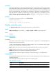
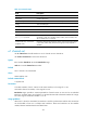
Table Of Contents
- Title Page
- Contents
- Ethernet interface configuration commands
- bandwidth
- combo enable
- default
- description
- display interface
- duplex
- flow-control
- flow-interval
- interface
- link-delay
- loopback
- port link-mode
- port link-mode interface-list
- reset counters interface
- shutdown
- speed
- broadcast-suppression
- display loopback-detection
- display counters
- display counters rate
- display port-group manual
- flow-interval
- group-member
- jumboframe enable
- loopback-detection control enable
- loopback-detection interval-time
- loopback-detection per-vlan enable
- mdi
- multicast-suppression
- port-group manual
- unicast-suppression
- virtual-cable-test
- mac-address
- mac-address valid-check
- mtu
- promiscuous
- qmtoken
- WAN interface configuration commands
- bandwidth
- default
- description
- link-delay
- shutdown
- async mode
- baudrate
- clock
- code
- country-code
- crc
- detect
- display interface analogmodem
- display interface aux
- display interface serial
- eliminate-pulse
- idle-mark
- invert receive-clock
- invert transmit-clock
- itf
- loopback
- looptest
- mtu
- physical-mode
- phy-mru
- reset counters interface
- reset counters interface
- reset counters interface
- reverse-rts
- timer hold
- virtualbaudrate
- autodeploy sms enable
- display cellular
- display cellular-ethernet
- display gps
- display interface cellular
- display interface cellular-ethernet
- display sms
- display sms statistics
- dm-port open
- gps mode
- gps nmea
- ip address cellular-allocated
- lte band
- mode cdma
- mode wcdma
- modem auto-recovery enable
- modem reboot
- modem response
- pin modify
- pin unlock
- pin verification
- pin verify
- plmn search
- plmn select
- profile create
- profile main
- recovery track
- reset counters interface cellular
- reset counters interface cellular-ethernet
- rssi
- sms delete
- sms forward
- sms send
- sms sending-enable
- snmp-agent trap enable sms
- standby rssi
- trust-imsi
- alarm
- cable (CE1/PRI interface)
- channel-set (CE1/PRI interface)
- clock (CE1/PRI interface)
- clock-change auto
- code (CE1/PRI interface)
- controller e1
- crc
- data-coding (CE1/PRI interface)
- detect-ais
- display controller e1
- error-diffusion restraint config
- error-diffusion restraint enable
- error-diffusion restraint restart-channel
- frame-format (CE1/PRI interface)
- idlecode (CE1/PRI interface)
- itf (CE1/PRI interface)
- loopback (CE1/PRI interface)
- looptest (CE1/PRI interface)
- pri-set (CE1/PRI interface)
- reset counters controller e1
- using (CE1/PRI interface)
- alarm (CT1/PRI interface)
- alarm-threshold
- bert (CT1/PRI interface)
- cable (CT1/PRI interface)
- channel-set (CT1/PRI interface)
- clock (CT1/PRI interface)
- code (CT1/PRI interface)
- controller t1
- crc
- data-coding (CT1/PRI interface)
- display controller t1
- error-diffusion restraint config
- error-diffusion restraint enable
- error-diffusion restraint restart-channel
- fdl
- frame-format (CT1/PRI interface)
- idlecode (CT1/PRI interface)
- itf (CT1/PRI interface)
- loopback (CT1/PRI interface)
- looptest (CT1/PRI interface)
- pri-set (CT1/PRI interface)
- reset counters controller t1
- sendloopcode
- clock-change auto
- crc
- display fe1
- fe1 alarm
- fe1 cable
- fe1 clock
- fe1 code
- fe1 data-coding
- fe1 frame-format
- fe1 idlecode
- fe1 itf
- fe1 loopback
- fe1 timeslot-list
- fe1 unframed
- crc
- display ft1
- ft1 alarm
- ft1 alarm-threshold
- ft1 bert
- ft1 cable
- ft1 clock
- ft1 code
- ft1 data-coding
- ft1 fdl
- ft1 frame-format
- ft1 idlecode
- ft1 itf
- ft1 loopback
- ft1 sendloopcode
- ft1 timeslot-list
- bert (CE3 interface)
- clock (CE3 interface)
- controller e3
- crc
- display controller e3
- e1 bert
- e1 channel-set
- e1 set clock
- e1 set frame-format
- e1 set loopback
- e1 shutdown
- e1 unframed
- fe3
- loopback (CE3 interface)
- national-bit
- reset counters controller e3
- using (CE3 interface)
- alarm (CT3 interface)
- bert (CT3 interface)
- cable (CT3 interface)
- clock (CT3 interface)
- controller t3
- crc
- display controller t3
- feac
- frame-format (CT3 interface)
- ft3
- loopback (CT3 interface)
- mdl (CT3 interface)
- reset counters controller t3
- t1 alarm
- t1 bert
- t1 channel-set
- t1 sendloopcode
- t1 set clock
- t1 set fdl
- t1 set frame-format
- t1 set loopback
- t1 show
- t1 shutdown
- t1 unframed
- using (CT3 interface)
- display interface bri
- loopback (ISDN BRI interface)
- mtu (ISDN BRI interface)
- reset counters interface
- ATM and DSL interface configuration commands
- bandwidth
- default
- description
- display interface atm
- interface atm
- reset atm interface
- reset counters interface
- shutdown
- cable (ATM E1 interface)
- cable (ATM T1 interface)
- clock
- clock-change auto
- code
- differential-delay
- display interface ima-group
- frame-format
- frame-length
- ima ima-group
- ima-clock
- ima-standard
- ima-test
- interface ima-group
- loopback
- min-active-links
- scramble
- cable
- clock
- frame-format
- loopback
- scramble
- clock
- flag
- frame-format
- loopback
- scramble
- activate
- adsl standard
- adsl tx-attenuation
- bootrom update file
- display dsl configuration
- display dsl status
- display dsl version
- activate
- display dsl configuration
- display dsl status
- display dsl version
- shdsl annex
- shdsl capability
- shdsl line-probing
- shdsl mode
- shdsl pam
- shdsl pbo
- shdsl psd
- shdsl rate
- shdsl snr-margin
- shdsl wire
- interface efm
- POS interface configuration commands
- CPOS interface configuration commands
- bandwidth
- clock
- controller cpos
- default
- description
- display controller cpos
- display controller cpos e1
- display controller cpos t1
- e1 channel-set
- e1 set clock
- e1 set flag
- e1 set frame-format
- e1 set loopback
- e1 shutdown
- e1 unframed
- flag
- frame-format
- loopback
- multiplex mode
- reset counters controller cpos
- shutdown
- t1 channel-set
- t1 set clock
- t1 set flag
- t1 set frame-format
- t1 set loopback
- t1 shutdown
- t1 unframed
- Loopback and null interface configuration commands
- Support and other resources
- Index

301
Table 41 Command output
Field Description
Cpos4/0 current state Current physical state of the CPOS interface.
Description Interface description.
Lower order path Alarm and error statistics of the lower order path.
TxFlag Sent overhead bytes.
RxFlag Received overhead bytes.
Alarm Alarm statistics.
Error Error statistics.
CT1 1 (1-1-1-1) is down
Current physical state of T1 channel 1 on interface CPOS 4/0. 1-1-1-1
represents in order VC-3 number, TUG-3 number, TUG-2 number, and
TU-12 number for an T1 channel.
Frame-format: ESF, clock: slave,
loopback: none
Information about the physical layer of the T1 channel: the framing format
is set to ESF; master clock (internal clock signal) is used; loopback is
disabled.
e1 channel-set
Use e1 channel-set to bundle timeslots on an E1 channel into one channel set.
Use undo e1 channel-set to remove the channel set.
Syntax
e1 e1-number channel-set set-number timeslot-list range
undo e1 e1-number channel-set set-number
Default
An E1 channel is not channelized.
Views
CPOS interface view
Default command level
2: System level
Parameters
e1-number: Number of an E1 channel on the CPOS interface, in the range of 1 to 63.
set-number: Channel set number, in the range of 0 to 30.
timeslot-list range: Specifies a comma-separated list of timeslot items. An item can be an individual
timeslot or a timeslot range. Use a hyphen (-) to separate the start and end timeslot numbers of a range.
The value range for the timeslot number is 1 to 31.
Usage guidelines
When the E1 channel is channelized, its timeslot 0 is used for synchronization and the other 31 timeslots
can be bundled to form one or multiple serial interfaces. These serial interfaces use the interface
number/channel number:channel set number format.