
R2511-HP MSR Router Series Interface Command Reference(V5)

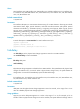
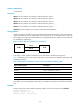
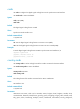
Table Of Contents
- Title Page
- Contents
- Ethernet interface configuration commands
- bandwidth
- combo enable
- default
- description
- display interface
- duplex
- flow-control
- flow-interval
- interface
- link-delay
- loopback
- port link-mode
- port link-mode interface-list
- reset counters interface
- shutdown
- speed
- broadcast-suppression
- display loopback-detection
- display counters
- display counters rate
- display port-group manual
- flow-interval
- group-member
- jumboframe enable
- loopback-detection control enable
- loopback-detection interval-time
- loopback-detection per-vlan enable
- mdi
- multicast-suppression
- port-group manual
- unicast-suppression
- virtual-cable-test
- mac-address
- mac-address valid-check
- mtu
- promiscuous
- qmtoken
- WAN interface configuration commands
- bandwidth
- default
- description
- link-delay
- shutdown
- async mode
- baudrate
- clock
- code
- country-code
- crc
- detect
- display interface analogmodem
- display interface aux
- display interface serial
- eliminate-pulse
- idle-mark
- invert receive-clock
- invert transmit-clock
- itf
- loopback
- looptest
- mtu
- physical-mode
- phy-mru
- reset counters interface
- reset counters interface
- reset counters interface
- reverse-rts
- timer hold
- virtualbaudrate
- autodeploy sms enable
- display cellular
- display cellular-ethernet
- display gps
- display interface cellular
- display interface cellular-ethernet
- display sms
- display sms statistics
- dm-port open
- gps mode
- gps nmea
- ip address cellular-allocated
- lte band
- mode cdma
- mode wcdma
- modem auto-recovery enable
- modem reboot
- modem response
- pin modify
- pin unlock
- pin verification
- pin verify
- plmn search
- plmn select
- profile create
- profile main
- recovery track
- reset counters interface cellular
- reset counters interface cellular-ethernet
- rssi
- sms delete
- sms forward
- sms send
- sms sending-enable
- snmp-agent trap enable sms
- standby rssi
- trust-imsi
- alarm
- cable (CE1/PRI interface)
- channel-set (CE1/PRI interface)
- clock (CE1/PRI interface)
- clock-change auto
- code (CE1/PRI interface)
- controller e1
- crc
- data-coding (CE1/PRI interface)
- detect-ais
- display controller e1
- error-diffusion restraint config
- error-diffusion restraint enable
- error-diffusion restraint restart-channel
- frame-format (CE1/PRI interface)
- idlecode (CE1/PRI interface)
- itf (CE1/PRI interface)
- loopback (CE1/PRI interface)
- looptest (CE1/PRI interface)
- pri-set (CE1/PRI interface)
- reset counters controller e1
- using (CE1/PRI interface)
- alarm (CT1/PRI interface)
- alarm-threshold
- bert (CT1/PRI interface)
- cable (CT1/PRI interface)
- channel-set (CT1/PRI interface)
- clock (CT1/PRI interface)
- code (CT1/PRI interface)
- controller t1
- crc
- data-coding (CT1/PRI interface)
- display controller t1
- error-diffusion restraint config
- error-diffusion restraint enable
- error-diffusion restraint restart-channel
- fdl
- frame-format (CT1/PRI interface)
- idlecode (CT1/PRI interface)
- itf (CT1/PRI interface)
- loopback (CT1/PRI interface)
- looptest (CT1/PRI interface)
- pri-set (CT1/PRI interface)
- reset counters controller t1
- sendloopcode
- clock-change auto
- crc
- display fe1
- fe1 alarm
- fe1 cable
- fe1 clock
- fe1 code
- fe1 data-coding
- fe1 frame-format
- fe1 idlecode
- fe1 itf
- fe1 loopback
- fe1 timeslot-list
- fe1 unframed
- crc
- display ft1
- ft1 alarm
- ft1 alarm-threshold
- ft1 bert
- ft1 cable
- ft1 clock
- ft1 code
- ft1 data-coding
- ft1 fdl
- ft1 frame-format
- ft1 idlecode
- ft1 itf
- ft1 loopback
- ft1 sendloopcode
- ft1 timeslot-list
- bert (CE3 interface)
- clock (CE3 interface)
- controller e3
- crc
- display controller e3
- e1 bert
- e1 channel-set
- e1 set clock
- e1 set frame-format
- e1 set loopback
- e1 shutdown
- e1 unframed
- fe3
- loopback (CE3 interface)
- national-bit
- reset counters controller e3
- using (CE3 interface)
- alarm (CT3 interface)
- bert (CT3 interface)
- cable (CT3 interface)
- clock (CT3 interface)
- controller t3
- crc
- display controller t3
- feac
- frame-format (CT3 interface)
- ft3
- loopback (CT3 interface)
- mdl (CT3 interface)
- reset counters controller t3
- t1 alarm
- t1 bert
- t1 channel-set
- t1 sendloopcode
- t1 set clock
- t1 set fdl
- t1 set frame-format
- t1 set loopback
- t1 show
- t1 shutdown
- t1 unframed
- using (CT3 interface)
- display interface bri
- loopback (ISDN BRI interface)
- mtu (ISDN BRI interface)
- reset counters interface
- ATM and DSL interface configuration commands
- bandwidth
- default
- description
- display interface atm
- interface atm
- reset atm interface
- reset counters interface
- shutdown
- cable (ATM E1 interface)
- cable (ATM T1 interface)
- clock
- clock-change auto
- code
- differential-delay
- display interface ima-group
- frame-format
- frame-length
- ima ima-group
- ima-clock
- ima-standard
- ima-test
- interface ima-group
- loopback
- min-active-links
- scramble
- cable
- clock
- frame-format
- loopback
- scramble
- clock
- flag
- frame-format
- loopback
- scramble
- activate
- adsl standard
- adsl tx-attenuation
- bootrom update file
- display dsl configuration
- display dsl status
- display dsl version
- activate
- display dsl configuration
- display dsl status
- display dsl version
- shdsl annex
- shdsl capability
- shdsl line-probing
- shdsl mode
- shdsl pam
- shdsl pbo
- shdsl psd
- shdsl rate
- shdsl snr-margin
- shdsl wire
- interface efm
- POS interface configuration commands
- CPOS interface configuration commands
- bandwidth
- clock
- controller cpos
- default
- description
- display controller cpos
- display controller cpos e1
- display controller cpos t1
- e1 channel-set
- e1 set clock
- e1 set flag
- e1 set frame-format
- e1 set loopback
- e1 shutdown
- e1 unframed
- flag
- frame-format
- loopback
- multiplex mode
- reset counters controller cpos
- shutdown
- t1 channel-set
- t1 set clock
- t1 set flag
- t1 set frame-format
- t1 set loopback
- t1 shutdown
- t1 unframed
- Loopback and null interface configuration commands
- Support and other resources
- Index
50
Default command level
2: System level
Parameters
dteclk1: Sets the interface clock selection mode to DTE clock option 1.
dteclk2: Sets the interface clock selection mode to DTE clock option 2.
dteclk3: Sets the interface clock selection mode to DTE clock option 3.
dteclk4: Sets the interface clock selection mode to DTE clock option 4.
dteclk5: Sets the interface clock selection mode to DTE clock option 5.
dteclkauto: Sets the interface clock selection mode to DTE auto-negotiation.
Usage guidelines
As DTE, the interface accepts the clock provided by the DCE. Because transmitting and receiving clocks
of synchronization devices are independent, the receiving clock of a DTE device can be either the
transmitting or receiving clock of the DCE device, so is the transmitting clock. Therefore, five clock options
are available for a DTE device.
Figure 1 Select a clock for a synchronous serial interface
In the figure, "TxClk" represents transmitting clock, and "RxClk" represents receiving clock.
Table 10 de
scribes the four clock selection options for a synchronous serial interface operating as DTE
and DCE, respectively.
Table 10 Clock options available for a synchronous serial interface operating as DTE
Clock selection o
p
tion Descri
p
tion
DTEclk1 TxClk = TxClk, RxClk = RxClk.
DTEclk2 TxClk = TxClk, RxClk = TxClk.
DTEclk3 TxClk = RxClk, RxClk = TxClk.
DTEclk4 TxClk = RxClk, RxClk = RxClk.
DTEclk5 TxClk = Local, RxClk = Local.
In the table, the clock preceding the equal sign (=) is the DTE clock and the one that follows is the DCE
clock.
Examples
# Set the synchronous serial interface operating as DTE to use the clock selection option dteclk2.
<Sysname> system-view
[Sysname] interface serial 2/0
[Sysname-Serial2/0] clock dteclk2