
R2511-HP MSR Router Series Interface Configuration Guide(V5)


30
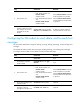
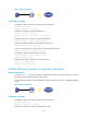
Figure 2 Network diagram
Configuration procedure
# Configure a dial access control rule for dialer access group 1.
<Router> system-view
[Router] dialer-rule 1 ip permit
# Assign an IP address to interface Cellular 0/0.
[Router] interface cellular 0/0
[Router-Cellular0/0] ip address 1.1.1.1 255.255.0.0
# Enable circular DCC (C-DCC) on interface Cellular 0/0.
[Router-Cellular0/0] dialer enable-circular
# Associate interface Cellular 0/0 with dialer access group 1.
[Router-Cellular0/0] dialer-group 1
# Set the interval for DCC to make the next call attempt to five seconds.
[Router-Cellular0/0] dialer timer enable 5
# Configure a dial string for calling a remote end.
[Router-Cellular0/0] dialer number 666666
[Router-Cellular0/0] quit
# Enable modem dial-in and dial-out on User interface 1.
[Router] user-interface tty 1
[Router-ui-tty1] modem both
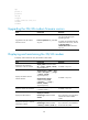
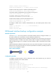
Cellular Ethernet interface configuration example
Network requirements
As shown in Figure 3, the router provides a USB 3G/4G module, and the PC dials up to access a
3G/4G network through Dial Control Center (DCC).
For more information about how DCC establishes dialup connections, see Layer 2—WAN Configuration
Guide.
Figure 3 Network diagram
Configuration procedure
# Configure a dial access control rule for dialer access group 1.
<Router> system-view
[Router] dialer-rule 1 ip permit
# Assign an IP address to interface Cellular-Ethernet 0/0.