
R2511-HP MSR Router Series Interface Configuration Guide(V5)

47
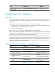
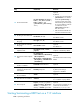
Step Command Remarks
15. Enable loopback.
loopback { local | payload |
remote }
Optional.
Disabled by default.
16. Send remote loopback control
code.
sendloopcode { fdl-ansi-llb-down |
fdl-ansi-llb-up | fdl-ansi-plb-down
| fdl-ansi-plb-up |
fdl-att-plb-down | fdl-att-plb-up |
inband-llb-down | inband-llb-up }
Optional.
No remote loopback control code
is sent by default.
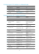
17. Set the intended bandwidth
for the CT1/PRI interface.
bandwidth bandwidth-value Optional.
18. Set the physical state change
suppression interval for the
CT1/PRI interface.
link-delay delay-time
Optional.
By default, state change
suppression is disabled.
19. Restore the default settings for
the CT1/PRI interface.
default Optional.
20. Shut down the CT1/PRI
interface.
shutdown
Optional.
A CT1/PRI interface is up by
default.
21. Return to system view.
quit N/A
22. Enter the view of the
synchronous serial interface
created on the CT1/PRI
interface.
interface serial
interface-number:set-number
or
interface serial
interface-number:23
N/A
23. Set the CRC mode.
crc { 16 | 32 | none }
Optional.
By default, 16-bit CRC is adopted..
Note:
1. B8ZS
= Bipolar 8 zero substitution; 2. ESF = Extended super frame; 3. LOS = Loss of signal; 4. AIS = Alarm
indication signal; 5. LFA = Loss of frame align
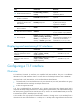
Starting/terminating a BERT test on a CT1/PRI interface
Bit error rate test (BERT) operates as follows:
The local end sends out a pattern, which is to be looped over somewhere on the line and back to the
local end. The local end then checks the received pattern for the bit error rate, and by so doing helps you
determine whether the condition of the line is good. To this end, you must configure loopback to allow
the transmitted pattern to loop back from somewhere on the line, for example, from the far-end interface
by placing the interface in far-end loopback.
You may view the state and result of the BERT test with the display controller t1 command.
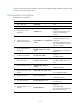
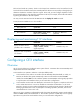
To start/terminate a BERT test on a CT1/PRI interface:
Step Command Remarks
1. Enter system view.
system-view N/A
2. Enter CT1/PRI interface view.
controller t1 number N/A