
R2511-HP MSR Router Series Interface Configuration Guide(V5)

64
• Permanent virtual circuit (PVC)
• Per-VC traffic shaping
• User-to-network Interface (UNI)
• RFC1483, Multiprotocol Encapsulation over ATM Adaptation Layer 5
• RFC2225, Classical IP and ARP over ATM
• RFC2390, Inverse Address Resolution Protocol
• F5 end to end loopback OAM
• ATM adaptation layer 5 (AAL5)
IMA
Overview
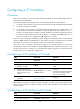
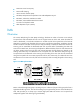
The Inverse Multiplexing for ATM (IMA) technology distributes an ATM cell stream across multiple
low-speed links and reassembles the cells into the original stream at the far end. When the ATM cell
stream is distributed, a round robin mechanism is invoked. Each of the low-speed links is fed with the
ATM cells in a specific order. The ATM cells sent in each round forms an IMA frame. In addition, the IMA
interface sends ICP cells (IMA control protocol cells) periodically to identify the IMA frames and for the
receiving end to reassemble the distributed ATM cells received. Before reassembling the ATM cells
received of an IMA frame, the receiving end adjusts the differential delay of the link and eliminates the
cell delay variation (CDV) using the ICP cells received. Because the IMA frames are aligned on the
sending end before they are distributed to the low-speed links, the differential delays among the
low-speed links can be detected on the receiving end according to the time when the cells transmitted
along the low-speed links arrive. IMA requires that cells be sent continuously. If no ATM cells are to be
sent between two successive ICP cells, filler cells are inserted, which are simply dropped on the receiving
end.
Figure 6 An IMA implementation
IMA is achieved through IMA groups. An IMA group is a collection of physical links grouped to form a
higher-bandwidth logical link. The rate of the IMA group is approximately the sum of the individual link
rates. IMA provides you a cheap way to transmit high-speed ATM cell streams over low-speed links
multiplexed together while allowing for great flexibility.