
R2511-HP MSR Router Series Interface Configuration Guide(V5)

65
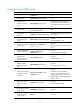
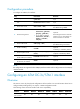
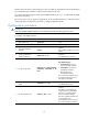
Configuring an IMA group
Ste
p
Command
Remarks
1. Enter system view
system-view N/A
2. Enter ATM E1/T1
interface view.
interface atm interface-number N/A
3. Add the current
interface to an IMA
group.
ima ima-group group-number
If the IMA group identified by the
group-number argument does not exist,
this command creates the IMA group
first.
4. Enter IMA group
interface view.
interface ima-group
group-interface-number
N/A
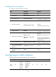
5. Assign an IP address to
the IMA group
interface.
ip address ip-address address-mask
By default, an IMA group interface has
no IP address.
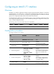
6. Set the number of the
cells an IMA frame
contains.
frame-length { 32 | 64 | 128 | 256 }
Optional.
The default setting is 128.
7. Set the clock mode for
the IMA group.
ima-clock { ctc [ link-number
number ] | itc }
Optional.
The default setting is common transmit
clock.
8. Set the standard to be
used by the IMA group.
ima-standard { alternate-v10 |
normal | standard-v10 |
standard-v11 }
Optional.
The default setting is normal.
9. Set the minimum
number of links
required for bringing
up the IMA group.
min-active-links number
Optional.
The default setting is 1.
10. Set the maximum
differential delay
allowed between the
links.
differential-delay milliseconds
Optional.
The default setting is 25 ms.
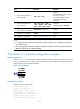
11. Enable IMA link test on
a link and specify the
test pattern.
ima-test [ link-number number ]
[ pattern-id id ]
Optional.
By default, link test is disabled.
If no link is specified, this command
enables IMA link test on the first link
added to the IMA group. The default test
pattern is 0xAA.
12. Set the power backoff
(PBO) value, which
reduces the transmit
power.
shdsl pbo { value | auto }
Optional.
The default setting is auto.
13. Set the intended
bandwidth for the IMA
group interface
bandwidth bandwidth-value Optional.
14. Restore the default
settings for the IMA
group interface
default Optional.