
R2511-HP MSR Router Series Interface Configuration Guide(V5)

67
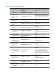
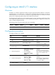
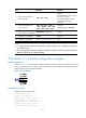
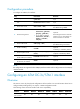
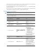
Step Command Remarks
8. Set the cable mode for the
ATM E1 interface.
cable { long | short }
Optional.
The default cable mode is long. In
this mode, the system
automatically adapts the cable
mode to the cable actually
connected.
9. Set the cable mode for the
ATM T1 interface.
cable { long { 0db | -7.5db |
-15db | -22.5db } | short { 133ft |
266ft | 399ft | 533ft | 655ft } }
Optional.
The default setting is long 0db.
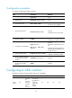
10. Set the intended bandwidth
for the ATM E1/T1 interface.
bandwidth bandwidth-value Optional.
11. Restore the default settings for
the ATM E1/T1 interface.
default Optional.
12. Configure an IMA group.
See "Configuring an IMA group."
N/A
NOTE:
• E1 configurations are supported on the IMA (E1) interface module and T1 configurations on the IMA
(T1) interface module.
• The line coding formats for IMA-E1 interfaces and IMA-T1 interfaces are fixed to high-density bipolar 3
(HDB3) and bipolar 8-zero substitution (B8ZS).
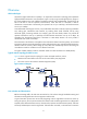
ATM IMA-E1/T1 interface configuration example
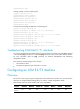
Network requirements
As shown in Figure 7, on the IMA-8E1 interface module of the router, create two IMA groups, each of
which is assigned two links; create two PVCs, setting their peer IP address to 10.10.10.10/24; and
configure them to support pseudo broadcast.
Figure 7 Network diagram
Configuration procedure
# Assign two links to IMA group 1.
<Sysname> system-view
[Sysname] interface atm 1/0
[Sysname-Atm1/0] undo ip address
[Sysname-Atm1/0] ima ima-group 1
[Sysname-Atm1/0] interface atm 1/2
[Sysname-Atm1/2] undo ip address
[Sysname-Atm1/2] ima ima-group 1