
R2511-HP MSR Router Series Interface Configuration Guide(V5)

69
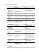
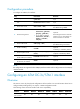
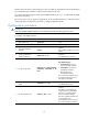
Configuration procedure
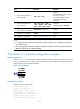
To configure an ATM E3/T3 interface:
Step Command Remarks
1. Enter system view.
system-view N/A
2. Enter ATM E3/T3 interface
view.
interface atm interface-number N/A
3. Set the clock mode.
clock { master | slave }
Optional.
The default setting is slave.
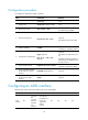
4. Set the framing format.
• On an ATM E3 interface:
frame-format { g751-adm |
g751-plcp | g832-adm }
• On an ATM T3 interface:
frame-format { cbit-adm |
cbit-plcp | m23-adm |
m23-plcp }
Optional.
The framing format for an ATM E3
interface is G.751 PLCP and for an
ATM T3 interface is C-bit PLCP.
5. Set the cable mode.
cable { long | short }
Optional.
The default setting is short haul.
6. Enable scrambling.
scramble
Optional.
Scrambling is enabled by default.
7. Set the loopback mode.
loopback { cell | local | payload |
remote }
Optional.
Loopback is disabled by default.
8. Set the intended bandwidth
for the ATM E3/T3 interface.
bandwidth bandwidth-value Optional.
9. Restore the default settings for
the ATM E3/T3 interface.
default Optional.
NOTE:
E3 configurations are supported on the ATM (E3) interface module and T3 configurations on the ATM (T3)
interface module.
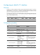
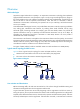
Configuring an ATM OC-3c/STM-1 interface
Overview
This section covers only the physical configurations of the interface. For more information about how to
configure ATM (including PVCs), see Layer 2—WAN Configuration Guide.
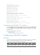
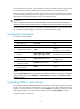
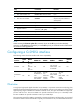
The following matrix shows the interface and router compatibility:
Interface MSR900 MSR93
X
MSR20-1
X
MSR20
MSR30 MSR50 MSR1000
ATM
OC-3c/STM-1
No No No No Yes Yes No