
R2511-HP MSR Router Series Interface Configuration Guide(V5)


77
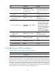
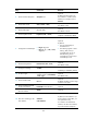
Task Command
Remarks
Display information about a
specified or all IMA group
interfaces.
display interface [ ima-group ] [ brief
[ down | description ] ] [ | { begin |
exclude | include } regular-expression ]
display interface ima-group
group-interface-number [ brief
[ description ] ] [ | { begin | exclude |
include } regular-expression ]
Available in any view.
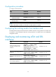
Clear the statistics on all PVCs on a
specified ATM interface.
reset atm interface [ atm
[ interface-number ] ]
Available in user view.
Clear the statistics on an ATM
interface.
reset counters interface [ atm
[ interface-number ] ]
Available in user view.
NOTE:
For those physical interfaces that are not connected to cables, shut down them using the shutdown
command to avoid anomalies resulted from interference.
Troubleshooting
Troubleshooting ATM interfaces
When diagnosing ATM interface problems, first test the interface with the ping command or the
extended ping command.
The ping command can test network connectivity. Extended ping command can be used to specify some
options in the IP header in addition to that function. For more information about the ping command, see
Network Management and Monitoring Configuration Guide.
If the interface cannot be pinged, check whether:
• The interface is down, which causes missing of its route in the routing table.
• The AAL5 encapsulation of the PVC is incorrect (for 155 Mbps ATM interfaces only).
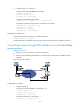
Troubleshooting DSL interfaces
Improper line operation is one of the faults that you might encounter in DSL applications. Such a fault is
likely to occur on whichever devices or nodes in the hierarchical broadband network architecture. It is
probably caused by the CPE device, copper wire, splitter, DSL port on DSLAM, or even the broadband
access server. For this reason, you should segment the network to locate the problem. DSLAM provides
you with abundant fault isolation methods and a complete guide, which are however, beyond the scope
of this document.
On the CPE, you may do the following when the problem occurs:
1. Read the LEDs for the DSL interface card.
When the DSL line is training, the LINK LED blinks. After the activation succeeds, the LINK LED
which should otherwise be OFF lights and stays ON. The Activity LED blinks when data is being
transmitted on the line.
2. Display the DSL state information with the display dsl status command.
The State of driver/chipsets field provides information on interface and transceiver states.