
R2511-HP MSR Router Series Interface Configuration Guide(V5)


82
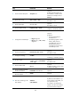
2. Configure POS 1/0 on Router B:
# Set the clock mode to master for the interface.
<RouterB> system-view
[RouterB] interface pos 1/0
[RouterB-Pos1/0] clock master
# Assign an IP address to the interface.
[RouterB-Pos1/0] ip address 10.110.1.11 255.255.255.0
# Configure the data link layer protocol and MTU for the interface.
[RouterB-Pos1/0] link-protocol ppp
[RouterB-Pos1/0] mtu 1500
[RouterB-Pos1/0] shutdown
[RouterB-Pos1/0] undo shutdown
Verifying the configuration
# Verify the POS interface settings, for example, on Router A.
<RouterA> display interface pos
# Verify that Router A and Router B can ping each other at the POS interfaces. (Details not shown.)
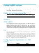
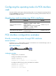
Connecting routers through POS interfaces across Frame Relay
Network requirements
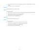
As shown in Figure 10:
• Routers A, B, and C are DTEs on a Frame Relay network.
• Router A uses Frame Relay sub-interfaces to connect Router B and Router C in different network
segments.
Figure 10 Network diagram
Configuration procedure
1. Configure Router A:
# Set the clock mode to slave on POS interface 1/0.
<RouterA> system-view
[RouterA] interface pos 1/0
[RouterA-Pos1/0] clock slave
# Enable Frame Relay on the interface.
[RouterA-Pos1/0] link-protocol fr