
R2511-HP MSR Router Series Interface Configuration Guide(V5)

83
[RouterA-Pos1/0] fr interface-type dte
[RouterA-Pos1/0] quit
# Create sub-interface 1 on the interface.
[RouterA] interface pos 1/0.1
[RouterA-Pos1/0.1] ip address 10.10.10.1 255.255.255.0
[RouterA-Pos1/0.1] fr map ip 10.10.10.2 50
[RouterA-Pos1/0.1] mtu 1500
[RouterA-Pos1/0.1] quit
# Create sub-interface 2 on the interface.
[RouterA] interface pos 1/0.2
[RouterA-Pos1/0.2] ip address 20.10.10.1 255.255.255.0
[RouterA-Pos1/0.2] fr map ip 20.10.10.2 60
[RouterA-Pos1/0.2] mtu 1500
[RouterA-Pos1/0.2] quit
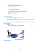
2. Configure Router B:
# Set the clock mode to slave on POS 1/0.
[RouterB] interface pos 1/0
[RouterB-Pos1/0] clock slave
# Configure Frame Relay encapsulation on the interface.
[RouterB-Pos1/0] link-protocol fr
[RouterB-Pos1/0] fr interface-type dte
[RouterB-Pos1/0] ip address 10.10.10.2 255.255.255.0
[RouterB-Pos1/0] fr map ip 10.10.10.1 70
[RouterB-Pos1/0] mtu 1500
3. Configure Router C in the same way Router B is configured. (Details not shown.)
Verifying the configuration
# Verify the POS interface settings.
<RouterA> display interface pos
# Verify that Router A and Router B can ping each other. (Details not shown.)
# Verify that Router A and Router C can ping each other. (Details not shown.)
Troubleshooting POS interfaces
Symptom 1
The physical state of the POS interface is down.
Solution
To resolve the problem:
• Verify that the POS interface is connected correctly to the remote port.
{ The transmit connector at one end must be connected to the receive connector at the other end.
{ The transmit and receive connectors of the POS interface must not be connected by the same
fiber. If they are connected by the same fiber, the display interface command displays the
"loopback detected" message, whether or not the loopback detection feature is enabled.