
R2511-HP MSR Router Series Interface Configuration Guide(V5)

87
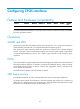
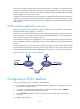
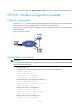
Figure 12 Process of multiplexing E1 channels to form STM-1
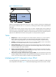
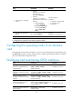
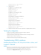
Figure 13 Process of multiplexing T1 channels to form STM-1
In actual applications, different countries and regions might adopt different multiplexing structures. To
ensure interoperability, the multiplex mode command is provided on CPOS interfaces. This allows you to
select the AU-3 or AU-4 multiplexing structure.
Calculating E1/T1 channel sequence numbers
Since CPOS interfaces adopt the byte interleaved multiplexing mode, the lower-order VCs are not
arranged in order in a higher-order VC. To understand how TU numbers are calculated, see the following
example where E1 channels are multiplexed to form STM-1 through the AU-4.
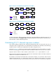
As shown in Figure 12, w
hen the AU-4 path is used, the multiplexing structure for 2 Mbps is 3-7-3. The
formula for calculating the TU-12 sequence numbers of different locations in the same VC-4 is as follows:
Sequence number of TU-12 = TUG-3 number + (TUG-2 number – 1) x 3 + (TU-12 Number – 1) x 21
The two TU-12s are adjacent to each other if they have the same TUG-3 number and TUG-2 number but
different TU-12 numbers with a difference of 1.
The numbers in the formula mentioned refer to the location numbers in a VC-4 frame. TUG-3 can be
numbered in the range of 1 to 3; TUG-2 in the range of 1 to 7 and TU-12 in the range of 1 to 3. TU-12
numbers indicate the order (E1 channel number) in which the 63 TU-12s in a VC-4 frame are multiplexed.
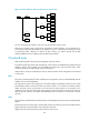
STM-1
TU-11TUG-2VC-3AU-3
TUG-3VC-4AU-4AUG-1
VC-11C-11
×1 ×1 ×3
×3
×7
×7
×4
C-11: 1.544Mbps
Multiplexing
Mapping
Aligning