
R2511-HP MSR Router Series Interface Configuration Guide(V5)

93
For more information about the display interface serial command, see Interface Command Reference.
CPOS-E1 interface configuration example
Network requirements
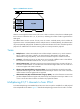
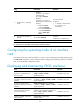
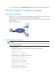
As shown in Figure 16, branch nodes Router B through Router H are uplinked to the central node Router
A through E1 links. Router A aggregate these E1 links with a CPOS interface.
Add one more E1 link on Router B to expand its capacity. In addition, bind the two E1 links through an
MP-group interface.
Figure 16 Network diagram
Configuration procedure
IMPORTANT:
For correct network synchronization, make sure the master clock mode is configured on the SONET/SDH
devices connected to the routers.
1. Configure Router A:
# Configure E1 channels 1 and 2 of CPOS 2/0 to operate in unframed mode.
<RouterA> system-view
[RouterA] controller cpos 2/0
[RouterA-Cpos2/0] e1 1 unframed
[RouterA-Cpos2/0] e1 2 unframed
# Create MP-group 1 and assign an IP address to it.
[RouterA] interface mp-group 1
[RouterA-Mp-group1] ip address 10.1.1.1 24
[RouterA-Mp-group1] quit
# Assign Serial 2/0/1:0 to MP-group 1.
[RouterA] interface serial2/0/1:0
[RouterA-Serial2/0/1:0] ppp mp mp-group 1
[RouterA-Serial2/0/1:0] quit
# Assign Serial 2/0/2:0 to MP-group 1.
[RouterA] interface serial2/0/2:0