
R2511-HP MSR Router Series IP Multicast Configuration Guide(V5)


98
Total number of downstreams: 1
1: Pos5/2
Protocol: pim-sm, UpTime: 00:13:16, Expires: 00:03:22
PIM-SM admin-scoped zone configuration example
Network requirements
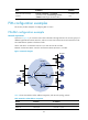
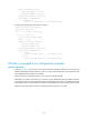
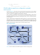
As shown in Figure 33, the receivers receive VOD information through multicast. The entire PIM-SM
domain is divided into admin-scoped zone 1, admin-scoped zone 2, and the global-scoped zone. Router
B, Router C, and Router D are ZBRs of the three domains, respectively.
Source 1 and Source 2 send different multicast informa t io n t o m u l t i c a s t g ro u p 239.1.1.1. H o s t A r e c eiv e s
the multicast information from Source 1 only, and Host B receives the multicast information from Source
2 only. Source 3 sends multicast information to multicast group 224.1.1.1. Host C is a multicast receiver for
this multicast group.
Serial 2/1 of Router B acts as a C-BSR and C-RP of admin-scoped zone 1, which serve the multicast group
range 239.0.0.0/8. Serial 2/1 of Router D acts as a C-BSR and C-RP of admin-scoped zone 2, which
also serve the multicast group range 239.0.0.0/8. Serial 2/1 of Router F acts as a C-BSR and a C-RP of
the global-scoped zone, which serve all the multicast groups other than those in the 239.0.0.0/8 range.
IGMPv2 runs between Router A, Router E, Router I, and their respective receivers.
Figure 33 Network diagram
Table 10 shows the interface and IP address assignment, and network topology scheme.
Router A
Router B
ZBR
Router C
ZBR
Router D
ZBR
Router E
Router HRouter I
Router F
Router G
Source 3
Source 1
Source 2
Receiver
Host A
S2/1
S2/
2
PO
S5
/1
Eth1/1
POS5/2 S2/1
S2/2
POS5/1
POS5/1
S2/1
S2/1
Eth1/1
S2/1
S2/2
Eth1/1
S2/1
S2/1 POS5/1
Eth1/
1
Eth1/1 Eth1/1
POS
5
/1
POS5/2 POS5/2S2/1
S2/1
Admin-scope 2
PIM-SM
Global-scope
Admin-scope 1
Receiver
Host B
Receiver
Host C