
R2511-HP MSR Router Series IP Multicast Configuration Guide(V5)

104
HoldTime: 150
Uptime: 00:00:32
Expires: 00:01:58
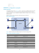
BIDIR-PIM configuration example
Network requirements
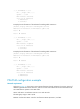
In the BIDIR-PIM domain shown in Figure 34, Source 1 and Source 2 send different multicast information
to multicast group 225.1.1.1. Host A and Host B receive multicast information from the two sources.
Serial 2/1 of Router C acts as a C-BSR, and loopback interface 0 of Switch C acts as a C-RP of the
BIDIR-PIM domain.
IGMPv2 runs between Router B and Host A and between Router D and Host B.
Figure 34 Network diagram
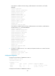
Table 11 shows the interface and IP address assignment, and network topology scheme.
Table 11 Interface and IP address assignment
Device Interface
IP
address
Router A Ethernet 1/1 192.168.1.1/24
Router A Serial 2/1 10.110.1.1/24
Router B Ethernet 1/1 192.168.2.1/24
Router B Serial 2/1 10.110.1.2/24
Router B Serial 2/2 10.110.2.1/24
Router C Serial 2/1 10.110.2.2/24
Router C Serial 2/2 10.110.3.1/24
Router C Loopback 0 1.1.1.1/32
Router D Ethernet 1/1 192.168.3.1/24
Router D Ethernet 1/2 192.168.4.1/24
BIDIR-PIM
Source 1 Source 2
Host A
Receiver 1
Router A
S2/1
S2/1
S2/2 S2/1
S2/2
S2/1
Eth1/1
Eth1/1
Et
h1/1
Eth1/2
Router D
Router C
Router B
Host B
Receiver 2
Loop0