
R2511-HP MSR Router Series IP Multicast Configuration Guide(V5)

131
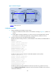
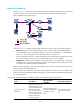
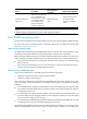
Figure 42 Network diagram
Configuration procedure
1. Assign an IP address and mask to each interface according to Figure 42. (Details not shown.)
2. Configure a GRE tunnel:
# On Router A, create Tunnel 0 and configure the IP address and mask for the interface.
<RouterA> system-view
[RouterA] interface tunnel 0
[RouterA-Tunnel0] ip address 50.1.1.1 24
# On Router A, specify the tunnel encapsulation mode as GRE over IPv4 and specify the source
and destination addresses of the interface.
[RouterA-Tunnel0] tunnel-protocol gre
[RouterA-Tunnel0] source 20.1.1.1
[RouterA-Tunnel0] destination 30.1.1.2
[RouterA-Tunnel0] quit
# On Router C, create Tunnel 0 and configure the IP address and mask for the interface.
<RouterC> system-view
[RouterC] interface tunnel 0
[RouterC-Tunnel0] ip address 50.1.1.2 24
# On Router C, specify the tunnel encapsulation mode as GRE over IPv4 and configure the source
and destination addresses of the interface.
[RouterC-Tunnel0] tunnel-protocol gre
[RouterC-Tunnel0] source 30.1.1.2
[RouterC-Tunnel0] destination 20.1.1.1
[RouterC-Tunnel0] quit
3. Configure OSPF:
# Configure OSPF on Router A.
[RouterA] ospf 1
[RouterA-ospf-1] area 0
[RouterA-ospf-1-area-0.0.0.0] network 10.1.1.0 0.0.0.255
[RouterA-ospf-1-area-0.0.0.0] network 20.1.1.0 0.0.0.255
[RouterA-ospf-1-area-0.0.0.0] network 50.1.1.0 0.0.0.255
[RouterA-ospf-1-area-0.0.0.0] quit
[RouterA-ospf-1] quit
# Configure OSPF on Router B.
Multicast router
Router A
Eth1/2
20.1.1.1/24
Eth1/2
30.1.1.1/24
Eth1/2
30.1.1.2/24
Eth1/1
20.1.1.2/24
Source Receiver
40.1.1.100/24
Eth1/1
40.1.1.1/24
10.1.1.100/24
Eth1/1
10.1.1.1/24
GRE tunnel
Tunnel0
50.1.1.1/24
Tunnel0
50.1.1.2/24
Unicast router
Router B
Multicast router
Router C