
R2511-HP MSR Router Series IP Multicast Configuration Guide(V5)


159
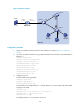
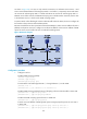
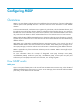
Figure 47 Network diagram
Configuration procedure
1. Assign an IP address and subnet mask to each interface according to Figure 47. (Details not
shown.)
2. On Router A, enable IP multicast routing, enable PIM-DM on each interface, and enable IGMP on
Ethernet 1/1.
<RouterA> system-view
[RouterA] multicast routing-enable
[RouterA] interface ethernet 1/1
[RouterA-Ethernet1/1] igmp enable
[RouterA-Ethernet1/1] pim dm
[RouterA-Ethernet1/1] quit
[RouterA] interface ethernet 1/2
[RouterA-Ethernet1/2] pim dm
[RouterA-Ethernet1/2] quit
3. Configure Switch A:
# Enable IGMP snooping globally.
<SwitchA> system-view
[SwitchA] igmp-snooping
[SwitchA-igmp-snooping] quit
# Create VLAN 100, assign Ethernet 1/1 through Ethernet 1/3 to this VLAN, and enable IGMP
snooping in the VLAN.
[SwitchA] vlan 100
[SwitchA-vlan100] port ethernet 1/1 to ethernet 1/3
[SwitchA-vlan100] igmp-snooping enable
[SwitchA-vlan100] quit
# Configure Ethernet 1/3 to be a static router port.
Source
1.1.1.1/24
Router A
IGMP querier
Eth1/1
10.1.1.1/24
Switch A
Switch B
Switch C
Eth1/1
E
t
h
1
/
2
E
t
h
1
/
3
E
t
h
1
/
1
E
t
h
1
/
1
E
t
h
1
/
3
E
t
h
1
/
5
Host A
Receiver
Host B
Host C
Receiver
VLAN 100
Eth1/2
1.1.1.2/24