
R2511-HP MSR Router Series IP Multicast Configuration Guide(V5)

182
Configure Loopback 0 as the C-BSR and C-RP of the related PIM-SM domain on Router B, Router C, and
Router E.
Set up MSDP peering relationships between the RPs of the PIM-SM domains to share multicast source
information among the PIM-SM domains.
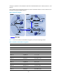
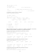
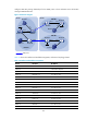
Figure 54 Network diagram
Table 14 shows the interface and IP address assignment, and network topology scheme.
Table 14 Interface and IP address assignment
Device Interface
IP address
Router A Ethernet 1/1 10.110.1.2/24
Router A Ethernet 1/2 10.110.2.1/24
Router A Ethernet 1/3 10.110.3.1/24
Router B Ethernet 1/1 10.110.1.1/24
Router B POS 5/0 192.168.1.1/24
Router B Loopback 0 1.1.1.1/32
Router C Ethernet 1/1 10.110.4.1/24
Router C Serial 2/0 192.168.3.1/24
Router C POS 5/0 192.168.1.2/24
Router C Loopback 0 2.2.2.2/32
Router D Ethernet 1/1 10.110.4.2/24
Router D Ethernet 1/2 10.110.5.1/24
Router E Ethernet 1/1 10.110.6.1/24
Router E Serial 2/0 192.168.3.2/24
Eth1
/
1
Eth1/1
Et
h1/3
Eth
1/2
Eth1/
2