
R2511-HP MSR Router Series IP Multicast Configuration Guide(V5)

191
1 1 0 0 0 0
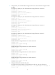
Peer's Address State Up/Down time AS SA Count Reset Count
10.110.2.1 Up 00:16:40 ? 13 0
Anycast RP configuration
Network requirements
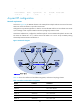
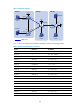
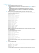
As shown in Figure 56, the PIM-SM domain in this example has multiple multicast sources and receivers.
OSPF runs within the domain to provide unicast routes.
Configure the Anycast RP application so that the receiver-side DRs and the source-side DRs can initiate
a Join message to their respective RPs that are the topologically nearest to them.
On Router B and Router D, configure the interface Loopback 10 as a C-BSR and Loopback 20 as a C-RP.
The router ID of Router B is 1.1.1.1, and the router ID of Router D is 2.2.2.2. Set up an MSDP peering
relationship between Router B and Router D.
Figure 56 Network diagram
Table 16 shows the interface and IP address assignment, and network topology scheme.
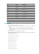
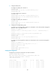
Table 16 Interface and IP address assignment
Device Interface
IP address
Source 1 — 10.110.5.100/24
Source 2 — 10.110.6.100/24
Router A Ethernet 1/1 10.110.5.1/24
Router A Serial 2/0 10.110.2.2/24
Router B Ethernet 1/1 10.110.1.1/24
Router B Serial 2/0 10.110.2.1/24
Loo
p0
Lo
op20
Loop20
Loo
p0
P
OS
5
/
0
P
O
S
5
/
0
P
OS
5
/
1
P
OS
5
/
0
S
2
/
0
S
2
/
0
S
2
/
0
S
2
/
0