
R2511-HP MSR Router Series IP Multicast Configuration Guide(V5)

218
MBGP configuration example
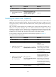
Network requirements
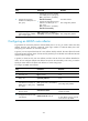
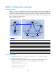
PIM-SM 1 is in AS 100, and PIM-SM 2 is in AS 200. OSPF is the IGP in the two ASs, and MBGP runs
between the two ASs to exchange multicast route information. The multicast source belongs to PIM-SM 1,
and the receiver belongs to PIM-SM 2. Configure the respective Loopback 0 of Router A and Router B as
the C-BSR and C-RP of the respective PIM-SM domains. Set up an MSDP peer relationship between
Router A and Router B through MBGP.
Figure 58 Network diagram
Device Interface IP address
Device
Interface
IP address
Source - 10.110.1.100/24
Router C
Eth1/1
10.110.2.1/24
Router A Eth1/1 10.110.1.1/24 S2/0 192.168.4.1/24
POS5/0 192.168.1.1/24
S2/1
192.168.2.2/24
Loop0 1.1.1.1/32
Loop0
3.3.3.3/32
Router B POS5/0 192.168.1.2/24 Router D S2/0 192.168.3.2/24
S2/0 192.168.2.1/24
S2/1
192.168.4.2/24
S2/1 192.168.3.1/24
Loop0
4.4.4.4/32
Loop0 2.2.2.2/32
Configuration procedure
1. Configure IP addresses for router interfaces as shown in Figure 58. (Details not shown.)
2. Configure OSPF. (Details not shown.)
3. Enable IP multicast routing, PIM-SM and IGMP, and configure a PIM-SM domain border:
# Enable IP multicast routing on Router A, and enable PIM-SM on each interface.
<RouterA> system-view
[RouterA] multicast routing-enable
[RouterA] interface ethernet 1/1
[RouterA-Ethernet1/1] pim sm
[RouterA-Ethernet1/1] quit
MBGP peers
AS 100 AS 200
Source
Receiver
Router A
Router B
Router C
Router D
POS5/0 POS5/0
S2/1 S2/0
Eth1/1
PIM-SM 1
PIM-SM 2
Loop0 Loop0
Loop0Loop0