
R2511-HP MSR Router Series IP Multicast Configuration Guide(V5)

235
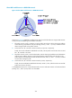
5. After the multicast traffic is switched from the share-MDT to the switch-MDT, PE 1 continues sending
MDT switchover messages periodically, so that subsequent PE devices with attached receivers can
join the switch-MDT. When a downstream PE device has no longer active receivers attached to it,
it leaves the switch-MDT.
For a given VPN instance, the share-MDT and the switch-MDT are both forwarding tunnels in the same
MD. A share-MDT is uniquely identified by a share-group address, and a switch-MDT is uniquely
identified by a switch-group address. Each share-group is uniquely associated with a set of switch-group
addresses, namely, a switch-group-pool.
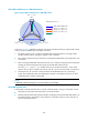
Backward switching from switch-MDT to share-MDT
After the VPN multicast traffic is switched to the switch-MDT, the multicast traffic conditions might change
and no longer meet the aforesaid switchover criterion. In this case, PE 1, as in the preceding example,
initiates a backward MDT switchover process. When any of the following criteria is met, the multicast
traffic is switched from the switch-MDT back to the share-MDT:
• The traffic rate of the VPN multicast data has fallen under the switchover threshold and stayed lower
than the threshold for a certain length of time (namely, the switch-holddown period).
• The associated switch-group-pool is changed and the switch-group address for encapsulating the
VPN multicast data is out of the new address pool.
• The ACL rule for controlling the switching of VPN multicast traffic from the share-MDT to the
switch-MDT is changed and the VPN multicast data fails to pass the new ACL rule.
Multi-AS MD VPN
If the nodes of a VPN network are allocated in multiple ASs, these VPN nodes must be interconnected.
To implement multi-AS VPN, VRF-to-VRF PE interconnectivity and multi-hop EBGP interconnectivity are
available.
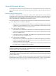
VRF-to-VRF PE interconnectivity
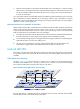
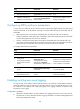
As shown in Figure 69, a VPN involves AS 1 and AS 2. PE 3 and PE 4 are the autonomous system
boundary routers (ASBRs) for AS 1 and AS 2, respectively. PE 3 and PE 4 are interconnected through
their respective VPN instance and treat each other as a CE device.
Figure 69 VPN instance-VPN instance interconnectivity
By using this method, a separate MD must be established within each AS, and VPN multicast traffic
between different ASs is transmitted between these MDs.