
R2511-HP MSR Router Series IP Multicast Configuration Guide(V5)


242
Item Network re
q
uirements
Unicast routing protocols and
MPLS
• Configure OSPF on the public network, and configure RIP between the PE
devices and the CE devices.
• Establish BGP peer connections between PE 1, PE 2 and PE 3 on their
respective Loopback 1 and exchange all VPN routes between them.
• Configure MPLS on the public network.
IP multicast routing
• Enable IP multicast routing on the P router.
• Enable IP multicast routing on the public network on PE 1, PE 2, and PE 3.
• Enable IP multicast routing in VPN instance a on PE 1, PE 2, and PE 3.
• Enable IP multicast routing in VPN instance b on PE 2 and PE 3.
• Enable IP multicast routing on CE a1, CE a2, CE a3, CE b1, and CE b2.
IGMP
• Run IGMPv2 on Ethernet 1/2 of PE 1.
• Run IGMPv2 on Ethernet 1/1 of CE a2, CE a3, and CE b2.
PIM
• Enable PIM-SM on all interfaces of the P router.
• Enable PIM-SM on all public and private network interfaces of PE 1, PE 2,
and PE 3.
• Enable PIM-SM on all interfaces of CE a1, CE a2, CE a3, CE b1, and CE
b2.
• Configure Loopback 1 of P as a public network C-BSR and C-RP (to work
for all multicast groups).
• Configure Loopback 1 of CE a2 as a C-BSR and a C-RP for VPN a (to work
for all multicast groups).
• Configure Loopback 2 of PE 3 as a C-BSR and a C-RP for VPN b (to work
for all multicast groups).
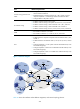
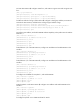
Figure 71 Network diagram
Table 20 shows the interface and IP address assignment, and network topology scheme.
Eth1/3
Eth1/1
Loop1
Loop1
Loop1
Loop1
Loop2
Loop1
E
t
h
1
/
1
E
t
h
1
/
2
E
t
h
1
/
1
E
t
h
1
/
2
E
t
h
1
/
3
E
t
h
1
/
1
E
t
h
1
/
1
E
t
h
1
/
3
E
t
h
1
/
2
E
t
h
1
/
1
E
t
h
1
/
2
E
t
h
1
/
2
E
t
h
1
/
2
E
t
h
1
/
3
E
t
h
1
/
2
Eth1/1
Eth1/1
E
t
h
1
/
1
E
t
h
1
/
2
E
t
h
1
/
3
S 2
S 1
P
PE 1
PE 2
PE 3
E
t
h
1
/
2
CE a1
CE a2
CE a3
CE b1
CE b2
Public
VPN b
VPN b
VPN a
VPN a
VPN a
E
t
h
1
/
3
R 1
R 2
R 3
R 4