
R2511-HP MSR Router Series IP Multicast Configuration Guide(V5)


255
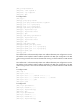
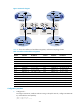
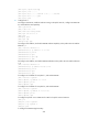
Figure 72 Network diagram
Table 21 shows the interface and IP address assignment, and network topology scheme.
Table 21 Interface and IP address assignment
Device Interface IP address
Device
Interface
IP address
S 1 — 10.11.5.2/24 R 1 — 10.11.8.2/24
S 2 — 10.11.6.2
/
24
R 2
—
10.11.7.2
/
24
PE 1 Ethernet 1/1 10.10.1.1
/
24
PE 3
Ethernet 1/1 10.10.2.1/24
PE 1 Ethernet 1/2 10.11.1.1/24 PE 3 Ethernet 1/2 192.168.1.2/24
PE 1 Ethernet 1/3 10.11.2.1
/
24
PE 3
Loopback 1 1.1.1.3
/
32
PE 1 Loopback 1 1.1.1.1
/
32
PE 3
Loopback 2 22.22.22.22
/
32
PE 2 Ethernet 1/1 10.10.1.2/24 PE 4 Ethernet 1/1 10.10.2.2/24
PE 2 Ethernet 1/2 192.168.1.1/24
PE 4
Ethernet 1/2 10.11.3.1/24
PE 2 Loopback 1 1.1.1.2/32
PE 4
Ethernet 1/3 10.11.4.1/32
PE 2 Loopback 2 11.11.11.11/32 PE 4 Loopback 2 1.1.1.4/32
CE a1 Ethernet 1/1 10.11.5.1/24
CE b1
Ethernet 1/1 10.11.6.1
/
24
CE a1 Ethernet 1/2 10.11.1.2
/
24
CE b1
Ethernet 1/2 10.11.2.2
/
24
CE a1 Loopback 0 2.2.2.2/32 CE b2 Ethernet 1/1 10.11.8.1/24
CE a2 Ethernet 1/1 10.11.7.1
/
24
CE b2
Ethernet 1/2 10.11.4.2
/
24
CE a2 Ethernet 1/2 10.11.3.2
/
24
CE b2
Loopback 0 3.3.3.3/32
Configuration procedure
1. Configure PE 1:
# Configure a Router ID, enable IP multicast routing on the public network, configure an MPLS LSR
ID, and enable the LDP capability.
<PE1> system-view
[PE1] router id 1.1.1.1
L
o
o
p
2
L
o
o
p
2
L
oop1
Lo
op
1