
R2511-HP MSR Router Series IP Multicast Configuration Guide(V5)

351
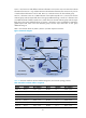
Source 1 and Source 2 send different multicast information to FF14::101. Host A receives the multicast
information from Source 1 only, and Host B receives the multicast information from Source 2 only. Source
3 sends multicast information to FF1E::202. Host C is a multicast receiver for this multicast group.
Serial 2/1 of Router B acts as a C-BSR and C-RP of IPv6 admin-scoped zone 1, which serve the IPv6
multicast groups with the Scope field value in their group addresses being 4. Serial 2/1 of Router D acts
as a C-BSR and C-RP of admin-scoped zone 2, which also serve the IPv6 multicast groups with the Scope
field value in their group addresses being 4. Serial 2/1 of Router F acts as a C-BSR and a C-RP of the
global-scoped zone, which serve IPv6 multicast groups with the Scope field value in their group
addresses being 14.
MLDv1 runs between Router A, Router E, Router I ,and their respective receivers.
Figure 97 Network diagram
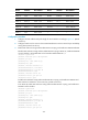
Table 29 shows the interface and IPv6 address assignment, and network topology scheme.
Table 29 Interface and IPv6 address assignment
Device Interface IPv6 address
Device
Interface IPv6 address
Router A Eth1/1 1001::1/64 Router D S2/1 3002::2/64
Router A S2/1 1002::1/64 Router D S2/2 6001::1/64
Router B Eth1/1 2001::1/64 Router D POS5/1 6002::1/64
Router B S2/1 1002::2/64 Router E Eth1/1 7001::1/64
Router B POS5/1 2002::1/64 Router E S2/1 3003::2/64
Router B POS5/2 2003::1/64 Router E S2/2 6001::2/64
Router C Eth1/1 3001::1/64 Router F S2/1 8001::1/64
Router A
Router B
ZBR
Router C
ZBR
Router D
ZBR
Router E
Router HRouter I
Router F
Router G
Source 3
Source 1
Source 2
Receiver
Host A
S2/1
S2/2
PO
S5
/1
Eth1/1
POS5/2 S2/1
S2/2
POS5/1
POS5/1
S2/1
S2/1
Eth1/1
S2/1
S2/2
Eth1/1
S2/1
S2/1 POS5/1
Eth1/1
Eth1/1 Eth1/1
PO
S5/
1
POS5/2 POS5/2S2/1
S2/1
IPv6 admin-scope 2
IPv6 PIM-SM
IPv6 global-scope
IPv6 admin-scope 1
Receiver
Host B
Receiver
Host C