
R2511-HP MSR Router Series IP Multicast Configuration Guide(V5)

363
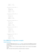
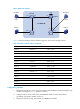
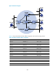
Figure 98 Network diagram
Table 30 shows the interface and IPv6 address assignment, and network topology scheme.
Table 30 Interface and IPv6 address assignment
Device Interface
IPv6
address
Router A Ethernet 1/1 1001::1/64
Router A Serial 2/1 1002::1/64
Router B Ethernet 1/1 2001::1/64
Router B Serial 2/1 1002::2/64
Router B Serial 2/2 2002::1/64
Router C Serial 2/1 2002::2/64
Router C Serial 2/2 3001::1/64
Router C Loopback 0 6001::1/128
Router D Ethernet 1/1 4001::1/64
Router D Ethernet 1/2 5001::1/64
Router D Serial 2/1 3001::2/64
Source 1 — 1001::2/64
Source 2 — 5001::2/64
Receiver 1 — 2001::2/64
Receiver 2 — 4001::2/64
Configuration procedure
1. Enable IPv6 forwarding on each router, and configure the IPv6 address and prefix length for each
interface according to Figure 98. (Details not shown.)
2. Conf
igure OSPFv3 on the routers in the IPv6 BIDIR-PIM domain to ensure network-layer
reachability among them. (Details not shown.)
3. Enable IPv6 multicast routing, IPv6 PIM-SM, IPv6 BIDIR-PIM, and MLD:
IPv6 BIDIR-PIM
Source 1 Source 2
Host A
Receiver 1
Router A
S2/1
S2/1
S2/2 S2/1
S2/2
S2/1
Eth1/1
Eth1/1
Et
h1
/1
Eth1/2
Router D
Router C
Router B
Host B
Receiver 2
Loop0