
R2511-HP MSR Router Series IP Multicast Configuration Guide(V5)

368
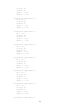
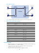
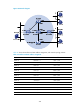
Figure 99 Network diagram
Table 31 shows the interface and IPv6 address assignment, and network topology scheme.
Table 31 Interface and IPv6 address assignment
Device Interface
IPv6 address
Router A Ethernet 1/1 1001::1/64
Router A Serial 2/0 1002::1/64
Router A POS 5/0 1003::1/64
Router B Ethernet 1/1 2001::1/64
Router B POS 5/0 2002::1/64
Router C Ethernet 1/1 2001::2/64
Router C POS 5/0 3001::1/64
Router D Ethernet 1/1 4001::1/64
Router D Serial 2/0 1002::2/64
Router D POS 5/0 4002::1/64
Router E POS 5/0 3001::2/64
Router E POS 5/1 2002::2/64
Router E POS 5/2 1003::2/64
Router E POS 5/3 4002::2/64
Ethernet
EthernetEthernet
N1N2
S2/0
S2/0