
R2511-HP MSR Router Series IP Multicast Configuration Guide(V5)

35
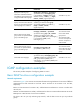
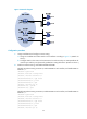
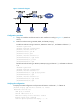
Figure 16 Network diagram
Table 6 Interface and IP address assignment
Device Interface IP address
Device
Interface
IP address
Source 1 — 133.133.1.1/24 Source 3 — 133.133.3.1/24
Source 2 — 133.133.2.1/24 Receiver — 133.133.4.1/24
Router A Eth1/1 133.133.1.2/24 Router C Eth1/1 133.133.3.2/24
Router A Eth1/2 192.168.1.1/24 Router C Eth1/2 192.168.3.1/24
Router A Eth1/3 192.168.4.2/24 Router C Eth1/3 192.168.2.2/24
Router B Eth1/1 133.133.2.2/24 Router D Eth1/1 133.133.4.2/24
Router B Eth1/2 192.168.1.2/24 Router D Eth1/2 192.168.3.2/24
Router B Eth1/3 192.168.2.1/24 Router D Eth1/3 192.168.4.1/24
Configuration procedure
1. Assign IP addresses and configure unicast routing:
a. Assign an IP address and subnet mask to each interface according to Figure 16. (Details not
shown.)
b. Configure OSPF on the routers in the PIM-SM domain to make sure they are interoperable at
the network layer and they can dynamically update their routing information. (Details not
shown.)
2. Enable IP multicast routing, enable PIM-SM on each interface, and enable IGMP and IGMP SSM
mapping on the host-side interface:
# Enable IP multicast routing on Router D, enable PIM-SM on each interface and enable IGMPv3
and IGMP SSM mapping on Ethernet 1/1.
<RouterD> system-view
[RouterD] multicast routing-enable
[RouterD] interface ethernet 1/1
[RouterD-Ethernet1/1] igmp enable
[RouterD-Ethernet1/1] igmp version 3
[RouterD-Ethernet1/1] igmp ssm-mapping enable
[RouterD-Ethernet1/1] pim sm
[RouterD-Ethernet1/1] quit