HP MSR Router Series Layer 2 - LAN Switching Configuration Guide(V5) Part number: 5998-2020 Software version: CMW520-R2511 Document version: 6PW103-20140128
Legal and notice information © Copyright 2014 Hewlett-Packard Development Company, L.P. No part of this documentation may be reproduced or transmitted in any form or by any means without prior written consent of Hewlett-Packard Development Company, L.P. The information contained herein is subject to change without notice.
Contents Configuring the MAC address table ·························································································································· 1 Overview············································································································································································ 1 How a MAC address entry is created ··················································································································· 1 Types of
Network requirements ··········································································································································· 21 Configuration procedure ······································································································································ 22 Verifying the configuration ··································································································································· 22 Configuring a voice VL
Configuring path costs of ports ···························································································································· 60 Configuration example ········································································································································· 60 Configuring the port priority ········································································································································· 61 Configuring the po
Layer 2 dynamic aggregation configuration example ······················································································ 92 Layer 3 static aggregation configuration example ···························································································· 94 Layer 3 dynamic aggregation configuration example ······················································································ 95 Configuring GVRP ·····································································
Application scenarios ········································································································································· 127 VLAN termination configuration task list ··················································································································· 128 Configuring unambiguous Dot1q termination··········································································································· 128 Configuring the TPID for VLAN-tagg
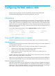
Configuring the MAC address table This book covers only the static, dynamic, and destination blackhole MAC address table. The MAC address table configuration tasks can be performed in any order. Overview To reduce single-destination packet flooding in a switched LAN, an Ethernet device uses a MAC address table for forwarding frames. This table describes from which port a MAC address (or host) can be reached.
To improve port security, you can bind specific user devices to the port by manually adding MAC address entries to the MAC address table of the device. Types of MAC address entries A MAC address table can contain the following types of entries: • Static entries—Manually added and never age out. • Dynamic entries—Manually added or dynamically learned, and might age out. • Destination Blackhole entries—Manually configured and never age out.
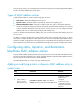
Adding or modifying a static or dynamic MAC address entry in interface view Step Command Remarks 1. Enter system view. system-view N/A 2. Enter Layer 2 Ethernet interface view. interface interface-type interface-number N/A 3. Add or modify a static or dynamic MAC address entry. mac-address { dynamic | static } mac-address vlan vlan-id By default, no MAC address entry is configured. Make sure you have created the VLAN and assigned the interface to the VLAN.
Step 3. Command Disable MAC address learning. Remarks By default, MAC address learning is enabled on each port. mac-address mac-learning disable The learned MAC address entries are removed after MAC address learning is disabled. Configuring the aging timer for dynamic MAC address entries The MAC address table uses an aging timer for dynamic MAC address entries for security and efficient use of table space.
Command MSR9 00 MSR93X MSR20 -1X MSR 20 MSR30 MSR50 MSR1000 Yes Available on only a MIM-FSW module. Yes mac-address max-mac-co unt No The count argument is in the range of 0 to 4096. No No The count argument is in the range of: • 0 to 8191 for MSR30-11E and MSR30-11F. Yes Available on only a FIC-FSW module. The count argument is in the range of 0 to 4096. Yes The count argument is in the range of 0 to 4096 • 0 to 4096 for others.
MAC address table configuration example Network requirements As shown in Figure 1: • Host A at MAC address 000f-e235-dc71 belongs to VLAN 1. • Host B at MAC address 000f-e235-abcd, which once behaved suspiciously on the network, also belongs to VLAN 1. Configure the MAC address table as follows: • To prevent MAC address spoofing, add a static entry for Host A in the MAC address table of the router. • Add a blackhole MAC address entry for Host B, so that all frames destined for the host are dropped.
--- 1 mac address(es) found --- # Display information about the destination blackhole MAC address table. [Router] display mac-address blackhole MAC ADDR VLAN ID STATE PORT INDEX AGING TIME(s) 000f-e235-abcd 1 Blackhole N/A NOAGED --- 1 mac address(es) found --- # Display the aging time of dynamic MAC address entries.
Layer 2 forwarding configuration Layer 2 forwarding includes the following categories: general, fast, inline, cut-through, and inter-VLAN. Because the HP MSR routers support only general Layer 2 forwarding among these categories, the following sections describe the working mechanism and configuration procedure about general Layer 2 forwarding only.
Configuring VLANs Overview Ethernet is a shared-media network based on the CSMA/CD mechanism. A LAN built by using Ethernet is both a collision domain and a broadcast domain. In a LAN with plenty of hosts, the LAN might be full of collisions and broadcasts. As a result, the LAN performance is degraded or even the LAN becomes unavailable. You can deploy bridges or Layer 2 switches in the LAN to reduce the collisions, but this cannot confine broadcasts.
The format of VLAN-tagged frames is defined in IEEE 802.1Q issued in 1999. As shown in Figure 3, in the header of a traditional Ethernet data frame, the field after the destination MAC address and the source MAC address (DA & SA) field is the Type field, which indicates the upper layer protocol type. Figure 3 Traditional Ethernet frame format IEEE 802.1Q inserts a 4-byte VLAN tag between the DA & SA field and the Type field to identify the VLAN information, as shown in Figure 4.
Protocols and standards IEEE 802.1Q, IEEE Standards for Local and Metropolitan Area Networks: Virtual Bridged Local Area Networks Configuring basic VLAN settings Configuration restrictions and guidelines • As the default VLAN, VLAN 1 cannot be created or removed. • You cannot manually create or remove VLANs reserved for special purposes. • To remove a dynamic VLAN, remove the configuration from the VLAN first, and then execute the undo vlan command.
Step Command Remarks 1. Enter system view. system-view N/A 2. Create a VLAN interface and enter VLAN interface view. interface vlan-interface vlan-interface-id If the specified VLAN interface already exists, you enter its view directly. 3. Assign an IP address to the VLAN interface. ip address ip-address { mask | mask-length } [ sub ] Optional. By default, no IP address is assigned to any VLAN interface. Optional. 4. Configure the description of the VLAN interface. description text 5.
to transmit packets of VLAN 2 and VLAN 3, and you must configure the ports interconnecting Device A and Device B as trunk ports and assign them to VLAN 2 and VLAN 3. • Hybrid port—A hybrid port allows traffic of some VLANs to pass through untagged and traffic of some other VLANs to pass through tagged. Usually, hybrid ports are configured to connect devices whose support for VLAN-tagged packets you are uncertain about.
Frame handling on a port Actions Access Trunk Incoming untagged frame Tags the frame with the PVID tag. Hybrid Determines whether the PVID is permitted on the port, as follows: • If yes, tags the frame with the PVID tag. • If not, drops the frame. • Receives the frame if Incoming tagged frame its VLAN ID is the same as the PVID. • Drops the frame if its VLAN ID is different from the PVID. • Receives the frame if its VLAN is permitted on the port.
Step Command Remarks • The configuration made in Layer 2 • Enter Layer 2 Ethernet interface view: interface interface-type interface-number 2. Enter interface view. • Enter Layer 2 aggregate interface view: interface bridge-aggregation interface-number 3. 4. Configure the link type of the ports as access. Assign the access ports to a VLAN. port link-type access Ethernet interface view applies only to the port.
Step 5. Command Configure the PVID of the trunk ports. Remarks port trunk pvid vlan vlan-id Optional. By default, the PVID is VLAN 1. To change the link type of a port from trunk to hybrid or from hybrid to trunk, you must set the link type to access first. After configuring the PVID for a trunk port, you must use the port trunk permit vlan command to configure the trunk port to allow packets from the PVID to pass through. Assigning a hybrid port to a VLAN A hybrid port can carry multiple VLANs.
Port-based VLAN configuration example Network requirements As shown in Figure 6, Host A and Host C belong to Department A, and access the enterprise network through different devices. Host B and Host D belong to Department B. They also access the enterprise network through different devices. To ensure communication security and avoid broadcast storms, VLANs are configured in the enterprise network to isolate Layer 2 traffic of different departments.
• Host A and Host C can ping each other successfully, but they both fail to ping Host B. • Host B and Host D can ping each other successfully, but they both fail to ping Host A. # Display information about VLANs 100 and 200 on Router A.
Configuring super VLANs Feature and hardware compatibility Feature Configuring super VLAN MSR90 0 No MSR93X No MSR20-1 X No MSR20 MSR30 MSR50 MSR1 000 No Available only on fixed Layer 2 Ethernet interfaces of MSR30-11E and MSR30-11F routers and on MSR30-10 routers installed with XMIM Layer 2 switching modules No No Overview Super VLAN, also called "VLAN aggregation," was introduced to save IP address space. A super VLAN is associated with multiple sub-VLANs.
Configuring sub-VLANs To configure multiple sub-VLANs, repeat these steps. To configure a sub-VLAN: Step Command Remarks 1. Enter system view. system-view N/A 2. Create a sub-VLAN and enter VLAN view. vlan vlan-id If the specified VLAN already exists, this command enters VLAN view only. Configuring a super VLAN Step Command Remarks 1. Enter system view. system-view N/A 2. Enter VLAN view.
Step Command Remarks 1. Enter system view. system-view N/A 2. Create a VLAN interface, and enter VLAN interface view. interface vlan-interface vlan-interface-id The value of vlan-interface-id must be the ID of the super VLAN. • Configure an IPv4 address: ip address ip-address { mask | mask-length } [ sub ] Configure the IP address of the VLAN interface. 3.
Figure 7 Network diagram Configuration procedure # Create VLAN 10, and configure its VLAN interface IP address as 10.0.0.1/24. system-view [Sysname] vlan 10 [Sysname-vlan10] quit [Sysname] interface vlan-interface 10 [Sysname-Vlan-interface10] ip address 10.0.0.1 255.255.255.0 # Enable local proxy ARP. [Sysname-Vlan-interface10] local-proxy-arp enable [Sysname-Vlan-interface10] quit # Create VLAN 2, and assign Ethernet 1/1 and Ethernet 1/2 to it.
display supervlan SuperVLAN ID : SubVLAN ID : 10 2-3 5 VLAN ID: 10 VLAN Type: static It is a Super VLAN. Route Interface: configured Ip Address: 10.0.0.1 Subnet Mask: 255.255.255.0 Description: VLAN 0010 Name: VLAN 0010 Tagged Ports: none Untagged Ports: none VLAN ID: 2 VLAN Type: static It is a Sub VLAN. Route Interface: configured Ip Address: 10.0.0.1 Subnet Mask: 255.255.255.
Untagged Ports: Ethernet1/5 Ethernet1/6 24
Configuring a voice VLAN Feature and hardware compatibility Feature Configuring a voice VLAN MSR90 0 No MSR93X No MSR20-1 X No MSR20 MSR30 MSR50 MSR100 0 No Available only on fixed Layer 2 Ethernet interfaces of MSR30-11E and MSR30-11F routers and on routers installed with MIM and XMIM Layer 2 switching modules Available only on routers installed with FIC Layer 2 Ethernet switching modules Yes Overview A voice VLAN is configured for voice traffic.
Number OUI address Vendor 5 0060-B900-0000 Philips/NEC phone 6 00E0-7500-0000 Polycom phone 7 00E0-BB00-0000 3Com phone In general, as the first 24 bits of a MAC address (in binary format), an OUI address is a globally unique identifier that IEEE assigns to a vendor. In this document, however, OUI addresses are addresses that the system uses to determine whether a received packet is a voice packet.
Figure 9 Only IP phones access the network Both modes forward tagged packets according to their tags. Table 2 and Table 3 list the configurations required for ports of different link types to support tagged or untagged voice traffic sent from IP phones when different voice VLAN assignment modes are configured. • When IP phones send tagged voice traffic If an IP phone sends tagged voice traffic and its accessing port is configured with 802.
Table 3 Required configurations on ports of different link types for them to support tagged voice traffic Port link type Voice VLAN assignment mode supported for untagged voice traffic Configuration requirements Access Manual Configure the PVID of the port as the voice VLAN. Trunk Manual Configure the PVID of the port as the voice VLAN and configure the port to permit packets from the voice VLAN to pass through.
Voice VLAN mode Packet processing mode • For untagged packets and packets that carry the voice VLAN tag: Normal mode The port does not determine the source MAC addresses of inbound packets. In this way, both voice traffic and non-voice traffic can be transmitted in the voice VLAN.
Step Command Remarks Optional. 7. 8. Configure the port to operate in automatic voice VLAN assignment mode. voice vlan mode auto Enable the voice VLAN feature. voice vlan vlan-id enable By default, the automatic voice VLAN assignment mode is enabled. Voice VLAN assignment modes on different ports are independent of one another. By default, the voice VLAN feature is disabled.
Step Command Remarks Optional. 7. Configure the voice VLAN as the PVID of the trunk or hybrid port. For the configuration procedure, see "Configuring VLANs." This operation is required for untagged inbound voice traffic and prohibited for tagged inbound voice traffic. 8. Enable voice VLAN on the port. voice vlan vlan-id enable By default, voice VLAN is disabled. Displaying and maintaining voice VLAN Task Command Remarks Display the voice VLAN state.
Figure 10 Network diagram Configuration procedure # Create VLAN 2 and VLAN 3. system-view [RouterA] vlan 2 to 3 Please wait... Done. # Set the voice VLAN aging time to 30 minutes. [RouterA] voice vlan aging 30 # Ethernet 1/1 might receive both voice traffic and data traffic at the same time. To ensure the quality of voice packets and effective bandwidth use, configure voice VLANs to operate in security mode. Configure the voice VLANs to transmit only voice packets.
[RouterA-Ethernet1/2] voice vlan mode auto [RouterA-Ethernet1/2] voice vlan 3 enable Verifying the configuration # Display OUI addresses, OUI address masks, and description strings.
Figure 11 Network diagram Router A Router B Internet Eth1/1 VLAN 2 Eth2/1 0755-2002 010-1001 OUI: 0011-2200-0000 Mask: ffff-ff00-0000 Configuration procedure # Configure the voice VLAN to operate in security mode. A voice VLAN operates in security mode by default. system-view [RouterA] voice vlan security enable # Add a recognizable OUI address 0011-2200-0000. [RouterA] voice vlan mac-address 0011-2200-0000 mask ffff-ff00-0000 description test # Create VLAN 2.
# Display the states of voice VLANs.
Configuring spanning tree protocols As a Layer 2 management protocol, the Spanning Tree Protocol (STP) eliminates Layer 2 loops by selectively blocking redundant links in a network, putting them in a standby state, which still allows for link redundancy. The recent versions of STP include the Rapid Spanning Tree Protocol (RSTP), Per VLAN Spanning Tree (PVST), and the Multiple Spanning Tree Protocol (MSTP). The MSR series routers do not support PVST. STP STP was developed based on the 802.
Basic concepts in STP Root bridge A tree network must have a root bridge. There is only one root bridge in the entire network. The entire network contains only one root bridge. All the other bridges in the network are called "leaf nodes." The root bridge is not permanent, but can change when the network topology changes. Upon initialization of a network, each device generates and periodically sends configuration BPDUs with itself as the root bridge.
STP algorithm The spanning tree calculation process described in the following sections is a simplified process for example only. Calculation process The STP algorithm uses the following calculation process: 1. State initialization. Upon initialization of a device, each port generates a BPDU with the device as the designated port, the device as the root bridge, 0 as the root path cost, and the device ID as the designated bridge ID. 2. Root bridge selection.
Table 6 Selecting the optimum configuration BPDU Step Actions Upon receiving a configuration BPDU on a port, the device compares the priority of the received configuration BPDU with that of the configuration BPDU generated by the port, and: • If the former priority is lower, the device discards the received configuration BPDU and 1 keeps the configuration BPDU that the port generated.
Table 7 Initial state of each device Device Device A Device B Device C 2. Port name Configuration BPDU on the port Port A1 {0, 0, 0, Port A1} Port A2 {0, 0, 0, Port A2} Port B1 {1, 0, 1, Port B1} Port B2 {1, 0, 1, Port B2} Port C1 {2, 0, 2, Port C1} Port C2 {2, 0, 2, Port C2} BPDUs comparison on each device. In Table 8, each configuration BPDU contains the following fields: root bridge ID, root path cost, designated bridge ID, and designated port ID.
Device Configuration BPDU on ports after comparison Comparison process • Device B compares the configuration BPDUs of all its ports, decides that the configuration BPDU of Port B1 is the optimum, and selects Port B1 as the root port with the configuration BPDU unchanged.
Device Configuration BPDU on ports after comparison Comparison process • Device C finds that the root path cost of Port C1 (10) (root path cost of the received configuration BPDU (0) plus path cost of Port C1 (10)) is larger than that of Port C2 (9) (root path cost of the received configuration BPDU (5) plus path cost of Port C2 (4)), decides that the configuration BPDU of Port C2 is the optimum, and selects Port C2 as the root port with the configuration BPDU unchanged.
However, the newly calculated configuration BPDU cannot be propagated throughout the network immediately, so the old root ports and designated ports that have not yet detected the topology change continue to forward data along the old path. If the new root ports and designated ports begin to forward data as soon as they are elected, a temporary loop might occur.
MSTP features Developed based on IEEE 802.1s, MSTP overcomes the limitations of STP and RSTP. In addition to supporting rapid network convergence, it also provides a better load sharing mechanism for redundant links by allowing data flows from different VLANs to be forwarded along separate paths. MSTP provides the following features: • Divides a switched network into multiple regions, each of which contains multiple spanning trees that are independent of one another.
Figure 16 Network diagram and topology of MST region 3 To MST region 2 To MST region 4 Device A MST region 3 A B A B C D C D Device B MSTI 1 A MSTI 2 B Regional root Device C Device D C D MSTI MSTI 0 VLAN 1 MSTI 1 VLAN 2&3 MSTI 2 Other VLANs MSTI 0 Topology of MSTIs in MST region 3 MST region A multiple spanning tree region (MST region) consists of multiple devices in a switched network and the network segments among them.
IST An internal spanning tree (IST) is a spanning tree that runs in an MST region. It is also called MSTI 0, a special MSTI to which all VLANs are mapped by default. In Figure 15, MSTI 0 is the IST in MST region 3. CIST The common and internal spanning tree (CIST) is a single spanning tree that connects all devices in a switched network. It consists of the ISTs in all MST regions and the CST.
MSTP calculation involves the following port roles: • Root port—Forwards data for a non-root bridge to the root bridge. The root bridge does not have any root port. • Designated port—Forwards data to the downstream network segment or device. • Alternate port—The backup port for a root port or master port. When the root port or master port is blocked, the alternate port takes over. • Backup port—The backup port of a designated port.
CIST calculation The calculation of a CIST tree is also the process of configuration BPDU comparison. During this process, the device with the highest priority is elected as the root bridge of the CIST. MSTP generates an IST within each MST region through calculation. At the same time, MSTP regards each MST region as a single device and generates a CST among these MST regions through calculation. The CST and ISTs constitute the CIST of the entire network.
sure that this VLAN is mapped to the CIST when you configure the VLAN-to-instance mapping table. For more information about GVRP, see "Configuring GVRP." • The spanning tree configurations made in system view take effect globally. Configurations made in Ethernet interface view take effect on the interface only. Configurations made in port group view take effect on all member ports in the port group. Configurations made in Layer 2 aggregate interface view take effect only on the aggregate interface.
Task Remarks Enabling outputting port state transition information Optional. Enabling the spanning tree feature Required. Configuring protection functions Optional. RSTP configuration task list Task Remarks Required. Setting the spanning tree mode Configuring the root bridge Configure the device to operate in RSTP mode. Configuring the root bridge or a secondary root bridge Optional. Configuring the device priority Optional. Configuring the network diameter of a switched network Optional.
Task Remarks Configuring protection functions Optional. MSTP configuration task list Task Remarks Optional. Configuring the root bridge Setting the spanning tree mode By default, the device operates in MSTP mode. Configuring an MST region Required. Configuring the root bridge or a secondary root bridge Optional. Configuring the device priority Optional. Configuring the maximum hops of an MST region Optional. Configuring the network diameter of a switched network Optional.
Task Remarks Performing mCheck Optional. Configuring digest snooping Optional. Configuring No Agreement Check Optional. Configuring protection functions Optional. Setting the spanning tree mode The spanning tree includes the following modes: • STP mode—All ports of the device send STP BPDUs. Select this mode when the peer device of a port supports only STP. • RSTP mode—All ports of the device send RSTP BPDUs.
Step Command Remarks Optional. 3. Configure the MST region name. 4. Configure the VLAN-to-instance mapping table. Configure the MSTP revision level of the MST region. revision-level level Display the MST region configurations that are not activated yet. check region-configuration Optional. 7. Activate MST region configuration manually. active region-configuration N/A 8. Display the activated configuration information of the MST region.
Step 1. Enter system view. 2. Configure the current device as the root bridge. Command Remarks system-view N/A • In STP/RSTP mode: stp root primary • In MSTP mode: stp [ instance instance-id ] root primary Use one of the commands. By default, a device does not function as the root bridge. Configuring the current device as a secondary root bridge of a specific spanning tree To configure the current device as a secondary root bridge of a specific spanning tree: Step 1. Enter system view. 2.
Configuring the maximum hops of an MST region By setting the maximum hops of an MST region, you can restrict the region size. The maximum hops configured on the regional root bridge will be used as the maximum hops of the MST region. Configuration BPDUs sent by the regional root bridge always have a hop count set to the maximum value. When a device receives this configuration BPDU, it decrements the hop count by 1 and uses the new hop count in BPDUs that it propagates.
• Hello time—The device detects whether a link failure has occurred with the hello time interval. The spanning tree sends a configuration BPDU during every hello time interval. If the device receives no configuration BPDUs within the hello time interval, it recalculates the spanning tree. • Max age—In the CIST of an MSTP network, the device uses the max age parameter to determine whether a configuration BPDU received by a port has expired. If it has, a new spanning tree calculation process starts.
Configuring the timeout factor The timeout factor is a parameter used to calculate the timeout time in the following formula: Timeout time = timeout factor × 3 × hello time. After the network topology stabilizes, each non-root-bridge device forwards configuration BPDUs to downstream devices at the interval of hello time to determine whether any link is faulty.
a temporary loop. Because a device does not determine whether a port is directly connected to a terminal, you must manually configure the port as an edge port. After that, the port can transit rapidly from the blocked state to the forwarding state. Configuration restrictions and guidelines • If BPDU guard is disabled, a port set as an edge port will become a non-edge port again if it receives a BPDU from another port. To restore the edge port, re-enable it.
legacy—The device calculates default path costs for ports based on a private standard. • Table 10 shows a comparison between link speeds and path costs for each of these standards. Table 10 Mappings between the link speed and the path cost Path cost Link speed Port type IEEE 802.1d-1998 IEEE 802.
the smallest value. This affects the reasonableness of forwarding path selection. To solve this problem, use dot1t as the standard for default path cost calculation, or manually set the path cost for a port (see "Configuring path costs of ports"). Configuration procedure To specify a standard for the device to use when it calculates the default path cost: Step Command Remarks 1. Enter system view. system-view N/A 2.
Configuring the port priority The priority of a port is an important factor in determining whether the port can be elected as the root port of a device. If all other conditions are the same, the port with the highest priority will be elected as the root port. On a spanning tree device, a port can have different priorities and play different roles in different spanning trees, so that data from different VLANs can be propagated along different physical paths to implement per-VLAN load balancing.
Step Enter system view. 1. Command Remarks system-view N/A • Enter Ethernet interface view or Layer 2 aggregate interface view: interface interface-type interface-number Enter interface view or port group view. 2. Use one of the commands. • Enter port group view: port-group manual port-group-name Configure the port link type. 3. stp point-to-point { auto | force-false | force-true } By default, the link type is auto and the port automatically detects the link type.
Step 3. Configure the mode that the port uses to recognize/send MSTP packets. Command Remarks stp compliance { auto | dot1s | legacy } The default setting is auto. Enabling outputting port state transition information In a large-scale spanning tree network, you can enable devices to output the port state transition information of all MSTIs or the specified MSTI in order to monitor the port states in real time. To enable outputting port state transition information: Step 1. Enter system view.
Performing mCheck If a port on a device that is running MSTP or RSTP connects to an STP device, this port automatically migrates to STP mode. However, it cannot automatically transit back to the original mode in the following situations: • The STP device is shut down or removed. • The STP device transits to MSTP or RSTP mode. Suppose Device A running STP, Device B with no spanning tree feature enabled, and Device C running RSTP or MSTP are connected in order.
To enable communication between an HP device and a third-party device, enable the digest snooping feature on the port that connects the HP device to the third-party device in the same MST region. Configuration prerequisites Before you enable digest snooping, make sure that associated devices of different vendors are connected and running spanning tree protocols.
Digest snooping configuration example Network requirements As shown in Figure 18, Router A and Router B connect to Router C, which is a third-party router. All these routers are in the same region. Enable digest snooping on the ports of Router A and Router B that connect to Router C, so that the three routers can communicate with one another. Figure 18 Network diagram Configuration procedure # Enable digest snooping on Ethernet 1/1 of Router A and enable global digest snooping on Router A.
Both RSTP and MSTP devices can perform rapid transition on a designated port only when the port receives an agreement packet from the downstream device. RSTP and MSTP devices have the following differences: • For MSTP, the root port of the downstream device sends an agreement packet only after it receives an agreement packet from the upstream device. • For RSTP, the downstream device sends an agreement packet regardless of whether an agreement packet is received from the upstream device.
• Connect a device to a third-party upstream device that supports spanning tree protocols with a point-to-point link. • Configure the same region name, revision level and VLAN-to-instance mappings on the two devices, assigning them to the same region. Configuration procedure To make the No Agreement Check feature take effect, enable it on the root port. To configure No Agreement Check: Step 1. Enter system view. Command Remarks system-view N/A • Enter Ethernet interface view or Layer 2 2.
Configuring protection functions A spanning tree device supports the following protection functions: • BPDU guard • Root guard • Loop guard • TC-BPDU guard Enabling BPDU guard For access layer devices, access ports can directly connect to user terminals (such as PCs) or file servers. Access ports are configured as edge ports to allow rapid transition.
Configure root guard on a designated port. You cannot configure root guard and loop guard on a port at the same time. To enable root guard: Step Enter system view. 1. Command Remarks system-view N/A • Enter Ethernet interface view or Layer 2 Enter interface view or port group view. 2. aggregate interface view: interface interface-type interface-number • Enter port group view: Use one of the commands. port-group manual port-group-name Enable the root guard function for the ports. 3.
Enabling TC-BPDU guard When a device receives topology change (TC) BPDUs (the BPDUs that notify devices of topology changes), the device flushes the forwarding address entries. If someone forges TC-BPDUs to attack the device, the device will receive a large number of TC-BPDUs within a short time and be busy with flushing forwarding address entries. This affects network stability.
Task Command Remarks Display MST region configuration information in effect. display stp region-configuration [ | { begin | exclude | include } regular-expression ] Available in any view. Display root bridge information for all MSTIs. display stp root [ | { begin | exclude | include } regular-expression ] Available in any view. Clear spanning tree statistics. reset stp [ interface interface-list ] Available in user view.
2. { Create VLAN 10, VLAN 20, and VLAN 40 on Router C. { Create VLAN 20, VLAN 30, and VLAN 40 on Router D. { Configure the ports on these routers as trunk ports and assign them to related VLANs. Configure Router A: # Enter MST region view and configure the MST region name as example. Map VLAN 10, VLAN 30, and VLAN 40 to MSTI 1, MSTI 3, and MSTI 4, respectively. Configure the revision level of the MST region as 0.
[RouterC-mst-region] instance 1 vlan 10 [RouterC-mst-region] instance 3 vlan 30 [RouterC-mst-region] instance 4 vlan 40 [RouterC-mst-region] revision-level 0 # Activate MST region configuration. [RouterC-mst-region] active region-configuration [RouterC-mst-region] quit # Specify the current router as the root bridge of MSTI 4. [RouterC] stp instance 4 root primary # Enable the spanning tree feature globally. [RouterC] stp enable Configure Router D: 5.
MSTID Port Role STP State Protection 0 Ethernet1/1 DESI FORWARDING NONE 0 Ethernet1/2 DESI FORWARDING NONE 0 Ethernet1/3 DESI FORWARDING NONE 1 Ethernet1/2 DESI FORWARDING NONE 1 Ethernet1/3 ROOT FORWARDING NONE 3 Ethernet1/1 DESI FORWARDING NONE 3 Ethernet1/3 DESI FORWARDING NONE # Display brief spanning tree information on Router C.
Configuring Ethernet link aggregation Overview Ethernet link aggregation, or simply link aggregation, combines multiple physical Ethernet ports into one logical link called an "aggregate link." Link aggregation delivers the following benefits: • Increases bandwidth beyond the limits of any single link. In an aggregate link, traffic is distributed across the member ports. • Improves link reliability. The member ports dynamically back up one another.
Aggregation states of member ports in an aggregation group A member port in an aggregation group can be in either of the following aggregation states: • Selected—A Selected port can forward user traffic. • Unselected—An Unselected port cannot forward user traffic. When a Selected port fails, an Unselected port might become a Selected port and forward user traffic. A Layer 3 aggregation group supports only one Selected port.
aggregation group, see "Choosing a reference port" in the section "Aggregating links in static mode." For information about how a reference port is selected in a dynamic link aggregation group, see "Choosing a reference port" in the section "Aggregating links in dynamic mode." Link aggregation modes Link aggregation can be done in dynamic mode or static mode. Dynamic link aggregation uses the IEEE 802.3ad LACP, but static link aggregation does not. Table 12 compares the two aggregation modes.
Type Description Port aggregation priority Determines the likelihood of a member port to be selected on a system. The higher the port aggregation priority, the higher the likelihood. 3. LACP timeout interval: LACP timeout interval specifies how long a member port waits to receive LACPDUs from the peer port. If a local member port fails to receive LACPDUs from the peer within three times the LACP timeout interval, the member port assumes that the peer port has failed.
Figure 25 Setting the aggregation state of a member port in a static aggregation group Set the aggregation state of a member port Yes Is there any hardware restriction? No No Is the port up? Yes Port attribute/class 2 configurations same as the reference port? No Yes More candidate ports than max.
Figure 26 Setting the state of a member port in a dynamic aggregation group Meanwhile, the system with the higher system ID, which has identified the aggregation state changes on the remote system, sets the aggregation state of local member ports as the same as their peer ports.
Configuration restrictions and guidelines When you configure a link aggregation group, follow these restrictions and guidelines: • To ensure stable aggregation state and service continuity, do not change port attributes or class-two configurations on any member port. If you must, make sure you understand its impact on the live network. Any port attribute or class-two configuration change might affect the aggregation state of link aggregation member ports and ongoing traffic.
Feature Reference Ethernet frame filtering Firewall in Security Configuration Guide IP source guard IP source guard in Security Configuration Guide 802.1X 802.1X in Security Configuration Guide Ports specified as source interfaces in portal-free rules Portal in Security Configuration Guide You cannot assign a port to a Layer 3 aggregation group if any of the features listed in Table 15 is configured on the port.
Step 4. Command a. interface interface-type interface-number Assign a Layer 2 Ethernet interface to the aggregation group. b. port link-aggregation group number Remarks Repeat this step to assign more Layer 2 Ethernet interfaces to the aggregation group. Optional. By default, the aggregation priority of a port is 32768. 5. Assign the port an aggregation priority.
Configuring a Layer 2 dynamic aggregation group The following matrix shows the feature and router compatibility: Feature MSR900 MSR93X MSR20-1X MSR20 MSR30 MSR50 MSR1000 Layer 2 dynamic aggregation group No Yes No No Yes Yes Yes To guarantee a successful dynamic aggregation, make sure the peer ports of the ports aggregated at one end are also aggregated. The two ends can automatically negotiate the aggregation state of each member port.
Step Command Remarks Optional. By default, the aggregation priority of a port is 32768. 7. Assign the port an aggregation priority. 8. Set the LACP timeout interval on the port to the short timeout interval (1 second).
Step Command Remarks Optional. By default, the aggregation priority of a port is 32768. 7. Assign the port an aggregation priority. 8. Set the LACP timeout interval on the port to the short timeout interval (1 second). When the number of ports eligible for becoming Selected ports exceeds the maximum number of Selected ports allowed in a dynamic aggregation group, changing the aggregation priority of a port might affect the aggregation state of ports in the dynamic aggregation group.
Configuring the MTU of a Layer 3 aggregate interface or subinterface The MTU of an interface affects IP packets fragmentation and reassembly on the interface. To change the MTU of a Layer 3 aggregate interface or subinterface: Step Command Remarks 1. Enter system view. system-view N/A 2. Enter Layer 3 aggregate interface or subinterface view. interface route-aggregation { interface-number | interface-number.subnumber } N/A 3. Configure the MTU of the Layer 3 aggregate interface or subinterface.
Step Command Remarks • Enter Layer 2 aggregate interface Enter aggregate interface view. 2. view: interface bridge-aggregation interface-number • Enter Layer 3 aggregate interface Use either command. view: interface route-aggregation interface-number Set the expected bandwidth for the aggregate interface. 3.
Step Command Remarks • Enter Layer 2 aggregate interface 2. Enter aggregate interface view. view: interface bridge-aggregation interface-number • Enter Layer 3 aggregate interface Use either command. view: interface route-aggregation interface-number 3. Restore the default settings for the aggregate interface or subinterface. N/A default Displaying and maintaining Ethernet link aggregation Task Display information about aggregate interfaces.
Layer 2 static aggregation configuration example Network requirements As shown in Figure 27, configure a Layer 2 static aggregation group on both Router A and Router B. Enable VLAN 10 at one end of the aggregate link to communicate with VLAN 10 at the other end, and VLAN 20 at one end to communicate with VLAN 20 at the other end. Figure 27 Network diagram Configuration procedure 1. Configure Router A: # Create VLAN 10, and assign port Ethernet 1/4 to VLAN 10.
[RouterA] interface bridge-aggregation 1 [RouterA-Bridge-Aggregation1] port link-type trunk [RouterA-Bridge-Aggregation1] port trunk permit vlan 10 20 Please wait... Done. Configuring Ethernet1/1... Done. Configuring Ethernet1/2... Done. Configuring Ethernet1/3... Done. [RouterA-Bridge-Aggregation1] quit 2. Configure Router B in the same way Router A is configured. Verifying the configuration # Display summary information about all aggregation groups on Router A.
Configuration procedure 1. Configure Router A: # Create VLAN 10, and assign the port Ethernet 1/4 to VLAN 10. system-view [RouterA] vlan 10 [RouterA-vlan10] port ethernet 1/4 [RouterA-vlan10] quit # Create VLAN 20, and assign the port Ethernet 1/5 to VLAN 20. [RouterA] vlan 20 [RouterA-vlan20] port ethernet 1/5 [RouterA-vlan20] quit # Create Layer 2 aggregate interface Bridge-Aggregation 1, and configure the link aggregation mode as dynamic.
AGG AGG Interface Mode Partner ID Select Unselect Share Ports Type Ports ------------------------------------------------------------------------------BAGG1 D 0x8000, 000f-e2ff-0002 3 0 NonS The output shows that link aggregation group 1 is a Layer 2 dynamic aggregation group and contains three Selected ports.
Actor System ID: 0x8000, 000f-e2ff-0001 AGG AGG Interface Mode Partner ID Select Unselect Share Ports Type Ports ------------------------------------------------------------------------------RAGG1 S none 1 2 NonS The output shows that link aggregation group 1 is a Layer 3 static aggregation group that contains one Selected port and two Unselected ports.
BAGG -- Bridge-Aggregation, RAGG -- Route-Aggregation Aggregation Mode: S -- Static, D -- Dynamic Loadsharing Type: Shar -- Loadsharing, NonS -- Non-Loadsharing Actor System ID: 0x8000, 000f-e2ff-0001 AGG AGG Interface Mode Partner ID Select Unselect Share Ports Type Ports ------------------------------------------------------------------------------RAGG1 D 0x8000, 000f-e2ff-0002 1 2 NonS The output shows that link aggregation group 1 is a Layer 3 dynamic aggregation group and contains one
Configuring GVRP The Generic Attribute Registration Protocol (GARP) provides a generic framework for devices in a switched LAN, such as end stations and switches, to register and deregister attribute values. The GARP VLAN Registration Protocol (GVRP) is a GARP application that registers and deregisters VLAN attributes. GVRP uses the operating mechanism of GARP to maintain and propagate dynamic VLAN registration information for GVRP devices on the network.
A GARP participant sends Join messages when it wishes to declare its attribute values or receives Join messages from other GARP participants. Join messages include the following types: { { • JoinEmpty—A GARP participant sends JoinEmpty messages to declare attribute values that it has not registered. JoinIn—A GARP participant sends JoinIn messages to declare attribute values that it has registered.
Figure 32 GARP PDU format Ethernet frame DA SA Length DSAP SSAP Protocol ID Ctrl GARP PDU Message 1 Attribute type ... Attribute event Message n End mark Attribute list Attribute 1 Attribute length ... Attribute n End mark Attribute value Table 16 describes the usage and values of fields contained in the GARP PDU portion of the Ethernet frames. Table 16 GARP PDU fields Field Description Value Protocol ID Protocol identifier for GARP. 0x0001.
The destination MAC addresses of GARP messages are multicast MAC addresses, and vary with GARP applications. For example, the destination MAC address of GVRP is 01-80-C2-00-00-21. GVRP GVRP overview As a GARP application, GVRP uses the operating mechanism of GARP to maintain and propagate dynamic VLAN registrations throughout a switched LAN.
Configuring basic GVRP functions Configuration prerequisites Before enabling GVRP on a port, you must enable GVRP globally. In addition, you can configure GVRP only on trunk ports, and you must assign the involved trunk ports to all dynamic VLANs. Configuration restrictions and guidelines • GVRP can work with STP, RSTP, or MSTP CIST. When GVRP runs on the CIST, blocked ports on the CIST cannot receive/send GVRP packets.
Step Configure the GVRP registration mode on the port. 7. Command Remarks gvrp registration { fixed | forbidden | normal } Optional. The default setting is normal. Configuring the GARP timers As shown in Table 17, the value ranges for GARP timers are dependent on one another: • If you want to set a value beyond the value range for a timer, you can change the value range by tuning the value of another related timer.
Step 1. Enter system view. Command Remarks system-view N/A Optional. 2. Configure the GARP LeaveAll timer. garp timer leaveall timer-value The default setting is 1000 centiseconds. The LeaveAll timer applies to all ports. • Enter Ethernet interface view or 3. Enter Ethernet interface view. Layer 2 aggregate interface view: interface interface-type interface-number Use one of the commands. • Enter port group view: port-group manual port-group-name Optional. 4. Configure the Hold timer.
Task Command Remarks Display the information about dynamic VLAN operations on ports. display gvrp vlan-operation interface interface-type interface-number [ | { begin | exclude | include } regular-expression ] Available in any view. Clear the GARP statistics on ports. reset garp statistics [ interface interface-list ] Available in user view. GVRP configuration examples The following sections give examples of how to configure GVRP in various modes.
[RouterB-Ethernet1/1] port trunk permit vlan all # Enable GVRP on trunk port Ethernet 1/1. [RouterB-Ethernet1/1] gvrp [RouterB-Ethernet1/1] quit # Create VLAN 3 (a static VLAN). [RouterB] vlan 3 [RouterB-vlan3] quit Verifying the configuration Use the display gvrp local-vlan command to display the local VLAN information that GVRP maintains on ports. For example: # Display the local VLAN information that GVRP maintains on port Ethernet 1/1 of Router A.
[RouterA-Ethernet1/1] gvrp [RouterA-Ethernet1/1] gvrp registration fixed [RouterA-Ethernet1/1] quit # Create VLAN 2 (a static VLAN). [RouterA] vlan 2 [RouterA-vlan2] quit 2. Configure Router B: # Enable GVRP globally. system-view [RouterB] gvrp # Configure port Ethernet 1/1 as a trunk port, and assign it to all VLANs.
Figure 35 Network diagram Configuration procedure 1. Configure Router A: # Enable GVRP globally. system-view [RouterA] gvrp # Configure port Ethernet 1/1 as a trunk port, and assign it to all VLANs. [RouterA] interface ethernet 1/1 [RouterA-Ethernet1/1] port link-type trunk [RouterA-Ethernet1/1] port trunk permit vlan all # Enable GVRP on Ethernet 1/1, and set the GVRP registration mode to forbidden on the port.
The output shows that information about VLAN 1 is registered through GVRP, but static VLAN information about VLAN 2 on the local router and dynamic VLAN information about VLAN 3 on Router B are not. # Display the local VLAN information maintained by GVRP on port Ethernet 1/1 of Router B.
Configuring LLDP Overview In a heterogeneous network, having a standard configuration exchange platform ensures that different types of network devices from different vendors can discover one another and exchange configuration information for the sake of interoperability and management. The Link Layer Discovery Protocol (LLDP) is specified in IEEE 802.1AB. The protocol operates on the data link layer to exchange device information between directly connected devices.
Field Description FCS Frame check sequence, a 32-bit CRC value used to determine the validity of the received Ethernet frame. 2. LLDPDU encapsulated in SNAP Figure 37 SNAP-encapsulated LLDPDU Table 19 Fields in a SNAP-encapsulated LLDPDU Field Description Destination MAC address MAC address to which the LLDPDU is advertised. It is fixed at 0x0180-C200-000E, a multicast MAC address. Source MAC address MAC address of the sending port. Type SNAP type for the upper layer protocol.
• Basic management TLVs • Organizationally (IEEE 802.1 and IEEE 802.3) specific TLVs • LLDP-MED (media endpoint discovery) TLVs Basic management TLVs are essential to device management. Organizationally specific TLVs and LLDP-MED TLVs are used for enhanced device management, and they are defined by standardization or other organizations and are optional to LLDPDUs. 1. Basic management TLVs: Table 20 lists the basic management TLV types.
NOTE: • HP devices support only receiving protocol identity TLVs. • Layer 3 Ethernet ports do not support IEEE 802.1 organizationally specific TLVs. 3. IEEE 802.3 organizationally specific TLVs Table 22 IEEE 802.3 organizationally specific TLVs Type Description MAC/PHY Configuration/Status Contains the bit-rate and duplex capabilities of the sending port, support for auto negotiation, enabling status of auto negotiation, and the current rate and duplex mode.
Type Description Software Revision Allows a terminal device to advertise its software version. Serial Number Allows a terminal device to advertise its serial number. Manufacturer Name Allows a terminal device to advertise its vendor name. Model Name Allows a terminal device to advertise its model name. Asset ID Allows a terminal device to advertise its asset ID. The typical case is that the user specifies the asset ID for the endpoint to assist directory management and asset tracking.
Receiving LLDPDUs An LLDP-enabled port that is operating in TxRx mode or Rx mode checks the validity of TLVs carried in every received LLDPDU. If valid, the information is saved and an aging timer is set for it based on the TTL value in the Time to Live TLV carried in the LLDPDU. If the TTL value is zero, the information ages out immediately. Protocols and standards • IEEE 802.
Step Command Remarks • Enter Layer 2/Layer 3 Ethernet interface Enter Ethernet interface view or port group view. 3. view: interface interface-type interface-number • Enter port group view: Use either command. port-group manual port-group-name Optional. Enable LLDP. 4. lldp enable By default, LLDP is enabled on a port. Setting the LLDP operating mode LLDP can operate in one of the following modes: • TxRx mode—A port in this mode can send and receive LLDPDUs.
Enabling LLDP polling With LLDP polling enabled, a device periodically searches for local configuration changes. On detecting a configuration change, the device sends LLDPDUs to inform neighboring devices of the change. To enable LLDP polling: Step 1. Enter system view. Command Remarks system-view N/A • Enter Layer 2/Layer 3 Ethernet interface 2. Enter Ethernet interface view or port group view. view: interface interface-type interface-number • Enter port group view: Use either command.
Configuring the management address and its encoding format LLDP encodes management addresses in numeric or character string format in management address TLVs. By default, management addresses are encoded in numeric format. If a neighbor encodes its management address in character string format, you must configure the encoding format of the management address as string on the connecting port to guarantee normal communication with the neighbor.
By setting the TTL multiplier, you can configure the TTL of locally sent LLDPDUs, which determines how long information about the local device can be saved on a neighboring device. The TTL is calculated with the following formula: TTL = Min (65535, (TTL multiplier × LLDPDU transmit interval)) As shown in the expression, the TTL can be up to 65535 seconds. TTLs greater than 65535 will be rounded down to 65535 seconds.
Step 1. Enter system view. Command Remarks system-view N/A • Enter Layer 2/Layer 3 Ethernet interface 2. Enter Ethernet interface view or port group view. view: interface interface-type interface-number • Enter port group view: Use either command. port-group manual port-group-name 3. Set the encapsulation format for LLDPDUs to SNAP. lldp encapsulation snap By default, Ethernet II encapsulation format applies.
voice VLAN directly specified for LLDP advertisement, the voice VLAN configured on the port, or the voice VLAN assigned by a server, depending on your configuration. To identify the voice VLAN advertised by LLDP, execute the display lldp local-information command, and examine the MED information fields in the command output. Specifying the voice VLAN to be advertised through LLDP Step Enter system view. 1.
Step Command Remarks • Enter Layer 2/Layer 3 Ethernet interface 2. Enter Ethernet interface view or port group view. view: interface interface-type interface-number • Enter port group view: Use either command. port-group manual port-group-name 3. Enable LLDP trapping. lldp notification remote-change enable By default, LLDP trapping is disabled. 4. Return to system view. quit N/A 5. Set the LLDP trap transmit interval. Optional.
Figure 40 Network diagram Configuration procedure 1. Configure Router A: # Enable LLDP globally. system-view [RouterA] lldp enable # Enable LLDP on Ethernet 1/1 and Ethernet 1/2. (You can skip this step because LLDP is enabled on ports by default.) Set the LLDP operating mode to Rx.
Trap interval : 5s Fast start times : 3 Port 1 [Ethernet1/1]: Port status of LLDP : Enable Admin status : Rx_Only Trap flag : No Polling interval : 0s Number of neighbors: 1 Number of MED neighbors : 1 Number of sent optional TLV : 0 Number of received unknown TLV : 0 Port 2 [Ethernet1/2]: Port status of LLDP : Enable Admin status : Rx_Only Trap flag : No Polling interval : 0s Number of neighbors: 1 Number of MED neighbors : 0 Number of sent optional TLV : 0 Number of receiv
Number of MED neighbors : 1 Number of CDP neighbors : 0 Number of sent optional TLV : 0 Number of received unknown TLV : 5 Port 2 [Ethernet1/2]: Port status of LLDP : Enable Admin status : Rx_Only Trap flag : No Polling interval : 0s Number of neighbors : 0 Number of MED neighbors : 0 Number of sent optional TLV : 0 Number of received unknown TLV : 0 As shown in the sample output, Ethernet 1/2 of Router A does not connect to any neighboring devices.
Configuring port isolation Overview Port isolation enables isolating Layer 2 traffic for data privacy and security without using VLANs. You can also use this feature to isolate the hosts in a VLAN from one another. The HP MSR series routers support only one isolation group that is created automatically as isolation group 1. You can neither remove the isolation group nor create other isolation groups. The number of ports assigned to the isolation group is not limited.
Port isolation configuration example Network requirements As shown in Figure 41, Ethernet 1/1, Ethernet 1/2, Ethernet 1/3, and Ethernet 1/4 are in the same VLAN. Configure the router to provide Internet access for LAN users Host A, Host B, and Host C, and isolate them from one another at Layer 2. Figure 41 Network diagram Configuration procedure # Assign ports Ethernet 1/1, Ethernet 1/2 and Ethernet 1/3 to the isolation group.
Configuring VLAN termination Overview VLAN termination assigns a VLAN-tagged packet received to the corresponding interface according to its VLAN tags, and then the interface removes its VLAN tags, and forwards it through Layer 3 or processes it in another way. Whether the packet is tagged before being sent out depends on the configuration of the outgoing interface. Before sending a packet, the port adds a VLAN tag to the packet according to the VLAN termination configuration on the port.
Figure 42 VLAN termination for inter-VLAN communication VLAN termination configuration task list Task Remarks Configuring unambiguous Dot1q termination Required. Configuring the TPID for VLAN-tagged packets Optional. Configuring unambiguous Dot1q termination Unambiguous Dot1q termination receives only VLAN-tagged packets whose outermost VLAN IDs match the specified VLAN ID and does not allow any other VLAN-tagged packets to pass through this subinterface.
Step Command Remarks • Enter Layer 3 Ethernet subinterface view: interface interface-type interface-number.subnumber • Enter Layer 3 aggregate subinterface 2. view: interface route-aggregation interface-number.subnumber Enter interface view. Use one of the commands. • Enter Layer 3 VE subinterface view: interface virtual-ethernet interface-number.subnumber • Enter VE-L3VPN-Access subinterface view: interface ve-l3vpn-access interface-number.subnumber 3.
Step 3. Command Set the TPID value in the outermost VLAN tag of packets received and sent by the interface Remarks dot1q ethernet-type hex-value Optional. The default setting is 0x8100. Unambiguous Dot1q termination configuration example Network requirements As shown in Figure 43, Host A and Host B are connected to Switch A, and Host C and Host D are connected to Switch B. Host A and Host C belong to VLAN 10, and Host B and Host D belong to VLAN 20. The IP addresses of subinterfaces Ethernet 1/1.
2. { Configure Host A's IP address as 1.1.1.1/8, and gateway IP address as 1.0.0.1/8. { Configure Host B's IP address as 2.2.2.2/8, and gateway IP address as 2.0.0.1/8. { Configure Host C's IP address as 3.3.3.3/8, and gateway IP address as 3.0.0.1/8. { Configure Host D's IP address as 4.4.4.4/8, and gateway IP address as 4.0.0.1/8. Configure Layer 2 Switch A: # Assign Ethernet 1/2 to VLAN 10.
Support and other resources Contacting HP For worldwide technical support information, see the HP support website: http://www.hp.
Conventions This section describes the conventions used in this documentation set. Command conventions Convention Description Boldface Bold text represents commands and keywords that you enter literally as shown. Italic Italic text represents arguments that you replace with actual values. [] Square brackets enclose syntax choices (keywords or arguments) that are optional. { x | y | ... } Braces enclose a set of required syntax choices separated by vertical bars, from which you select one.
Network topology icons Represents a generic network device, such as a router, switch, or firewall. Represents a routing-capable device, such as a router or Layer 3 switch. Represents a generic switch, such as a Layer 2 or Layer 3 switch, or a router that supports Layer 2 forwarding and other Layer 2 features. Represents an access controller, a unified wired-WLAN module, or the switching engine on a unified wired-WLAN switch. Represents an access point.
Index ABCDEFGLMOPRSUVW Configuring the aging timer for dynamic MAC address entries,4 A Assigning ports to the isolation group,125 Configuring the device priority,54 B Configuring the GARP timers,102 Basic LLDP configuration example,121 Configuring the MAC learning limit on ports,4 Configuring the maximum hops of an MST region,55 C Configuring the maximum port rate,57 Configuration prerequisites,29 Configuring the mode a port uses to recognize and send MSTP packets,62 Configuration restrictions an
Ethernet link aggregation configuration task list,82 P F Performing basic LLDP configuration,114 Feature and hardware compatibility,25 Performing mCheck,64 Port isolation configuration example,126 Feature and hardware compatibility,19 Protocols and standards,48 G R GVRP configuration examples,104 Related information,132 GVRP configuration task list,100 RSTP,43 L S LLDP configuration task list,114 Setting the spanning tree mode,52 M Spanning tree configuration task lists,48 MAC address ta