
R2511-HP MSR Router Series Layer 2 - LAN Switching Configuration Guide(V5)

95
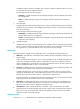
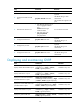
Actor System ID: 0x8000, 000f-e2ff-0001
AGG AGG Partner ID Select Unselect Share
Interface Mode Ports Ports Type
-------------------------------------------------------------------------------
RAGG1 S none 1 2 NonS
The output shows that link aggregation group 1 is a Layer 3 static aggregation group that contains one
Selected port and two Unselected ports.
Layer 3 dynamic aggregation configuration example
Network requirements
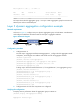
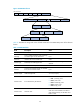
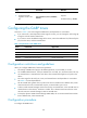
As shown in Figure 30, configure a Layer 3 dynamic aggregation group on both Router A and Router B
and configure IP addresses and subnet masks for the Layer 3 aggregate interfaces.
Figure 30 Network diagram
Configuration procedure
1. Configure Router A:
# Create Layer 3 aggregate interface Route-Aggregation 1, configure the link aggregation mode
as dynamic, and configure an IP address and subnet mask for the aggregate interface.
<RouterA> system-view
[RouterA] interface route-aggregation 1
[RouterA-Route-Aggregation1] link-aggregation mode dynamic
[RouterA-Route-Aggregation1] ip address 192.168.1.1 24
[RouterA-Route-Aggregation1] quit
# Assign Layer 3 Ethernet interfaces Ethernet 1/1 through Ethernet 1/3 to aggregation group 1.
[RouterA] interface ethernet 1/1
[RouterA-Ethernet1/1] port link-aggregation group 1
[RouterA-Ethernet1/1] quit
[RouterA] interface ethernet 1/2
[RouterA-Ethernet1/2] port link-aggregation group 1
[RouterA-Ethernet1/2] quit
[RouterA] interface ethernet 1/3
[RouterA-Ethernet1/3] port link-aggregation group 1
[RouterA-Ethernet1/3] quit
2. Configure Router B in the same way Router A is configured.
Verifying the configuration
# Display summary information about all aggregation groups on Router A.
[RouterA] display link-aggregation summary
Aggregation Interface Type: