
R2511-HP MSR Router Series Layer 2 - LAN Switching Configuration Guide(V5)


107
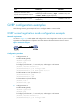
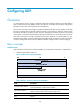
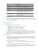
Figure 35 Network diagram
Configuration procedure
1. Configure Router A:
# Enable GVRP globally.
<RouterA> system-view
[RouterA] gvrp
# Configure port Ethernet 1/1 as a trunk port, and assign it to all VLANs.
[RouterA] interface ethernet 1/1
[RouterA-Ethernet1/1] port link-type trunk
[RouterA-Ethernet1/1] port trunk permit vlan all
# Enable GVRP on Ethernet 1/1, and set the GVRP registration mode to forbidden on the port.
[RouterA-Ethernet1/1] gvrp
[RouterA-Ethernet1/1] gvrp registration forbidden
[RouterA-Ethernet1/1] quit
# Create VLAN 2 (a static VLAN).
[RouterA] vlan 2
[RouterA-vlan2] quit
2. Configure Router B:
# Enable GVRP globally.
<RouterB> system-view
[RouterB] gvrp
# Configure port Ethernet 1/1 as a trunk port, and assign it to all VLANs.
[RouterB] interface ethernet 1/1
[RouterB-Ethernet1/1] port link-type trunk
[RouterB-Ethernet1/1] port trunk permit vlan all
# Enable GVRP on Ethernet 1/1, and set the GVRP registration mode to forbidden on the port.
[RouterB-Ethernet1/1] gvrp
[RouterB-Ethernet1/1] gvrp registration forbidden
[RouterB-Ethernet1/1] quit
# Create VLAN 3 (a static VLAN).
[RouterB] vlan 3
[RouterB-vlan3] quit
Verifying the configuration
Use the display gvrp local-vlan command to display the local VLAN information that GVRP maintains on
ports. For example:
# Display the local VLAN information maintained by GVRP on port Ethernet 1/1 of Router A.
[RouterA] display gvrp local-vlan interface ethernet 1/1
Following VLANs exist in GVRP local database:
1(default)