
R2511-HP MSR Router Series Layer 2 - LAN Switching Configuration Guide(V5)

126
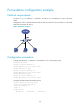
Port isolation configuration example
Network requirements
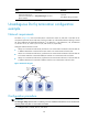
As shown in Figure 41, Ethernet 1/1, Ethernet 1/2, Ethernet 1/3, and Ethernet 1/4 are in the same
VLAN.
Configure the router to provide Internet access for LAN users Host A, Host B, and Host C, and isolate
them from one another at Layer 2.
Figure 41 Network diagram
Configuration procedure
# Assign ports Ethernet 1/1, Ethernet 1/2 and Ethernet 1/3 to the isolation group.
<Router> system-view
[Router] interface ethernet 1/1
[Router-Ethernet1/1] port-isolate enable
[Router-Ethernet1/1] quit
[Router] interface ethernet 1/2
[Router-Ethernet1/2] port-isolate enable
[Router-Ethernet1/2] quit
[Router] interface ethernet 1/3
[Router-Ethernet1/3] port-isolate enable
# Display information about the isolation group.
<Router> display port-isolate group
Port-isolate group information:
Uplink port support: NO
Group ID: 1
Group members:
Ethernet1/1 Ethernet1/2 Ethernet1/3