
R2511-HP MSR Router Series Layer 2 - LAN Switching Configuration Guide(V5)

130
Ste
p
Command
Remarks
3. Set the TPID value in the
outermost VLAN tag of
packets received and sent
by the interface
dot1q ethernet-type hex-value
Optional.
The default setting is 0x8100.
Unambiguous Dot1q termination configuration
example
Network requirements
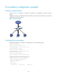
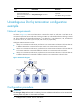
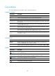
As shown in Figure 43, Host A and Host B are connected to Switch A, and Host C and Host D are
connected to Switch B. Host A and Host C belong to VLAN 10, and Host B and Host D belong to VLAN
20. The IP addresses of subinterfaces Ethernet 1/1.10, Ethernet 1/1.20, Ethernet 2/1.10, and Ethernet
2/1.20 are 1.0.0.1/8, 2.0.0.1/8, 3.0.0.1/8, and 4.0.0.1/8, respectively.
Configure VLAN termination so that:
• Host A can communicate with Host B, and Host C can communicate with Host D. The hosts that are
in different VLANs but connected to the same switch can communicate with each other.
• Host A can communicate with Host C, and Host B can communicate with Host D. The hosts that are
in the same VLAN but connected to different switches can communicate with each other.
• Host A can communicate with Host D, and Host B can communicate with Host C. The hosts that are
in different VLANs and connected to different switches can communicate with each other.
Figure 43 Network diagram
Configuration procedure
IMPORTANT:
The vlan-type dot1q vid command is mandatory, because an Ethernet subinterface can be activated and
transmit packets only after it is associated with VLANs.
1. Configure Host A, Host B, Host C, and Host D:
Host B
2.2.2.2/8
VLAN 20
Switch A Switch B
Eth1/1.10
1.0.0.1/8
VLAN 10
Router
Eth1/2 Eth1/3
Eth1/1
Eth2/1.20
4.0.0.1/8
VLAN 20
Eth1/2
Eth1/1.20
2.0.0.1/8
VLAN 20
Eth2/1.10
3.0.0.1/8
VLAN 10
Host A
1.1.1.1/8
VLAN 10
Eth1/1
Eth1/3
Host C
3.3.3.3/8
VLAN 10
Host D
4.4.4.4/8
VLAN 20