
R2511-HP MSR Router Series Layer 2 - LAN Switching Configuration Guide(V5)

17
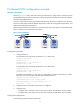
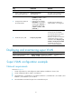
Port-based VLAN configuration example
Network requirements
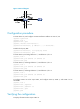
As shown in Figure 6, Host A and Host C belong to Department A, and access the enterprise network
through different devices. Host B and Host D belong to Department B. They also access the enterprise
network through different devices.
To ensure communication security and avoid broadcast storms, VLANs are configured in the enterprise
network to isolate Layer 2 traffic of different departments. VLAN 100 is assigned to Department A, and
VLAN 200 is assigned to Department B.
Make sure hosts within the same VLAN can communicate with each other. Host A can communicate with
Host C, and Host B can communicate with Host D.
Figure 6 Network diagram
Configuration procedure
1. Configure Router A:
# Create VLAN 100, and assign port Ethernet 1/1 to VLAN 100.
<RouterA> system-view
[RouterA] vlan 100
[RouterA-vlan100] port ethernet 1/1
[RouterA-vlan100] quit
# Create VLAN 200, and assign port Ethernet 1/2 to VLAN 200.
[RouterA] vlan 200
[RouterA-vlan200] port ethernet 1/2
[RouterA-vlan200] quit
# Configure port Ethernet 1/3 as a trunk port, and assign it to VLANs 100 and 200, to enable
Ethernet 1/3 to forward traffic of VLANs 100 and 200 to Router B.
[RouterA] interface ethernet 1/3
[RouterA-Ethernet1/3] port link-type trunk
[RouterA-Ethernet1/3] port trunk permit vlan 100 200
Please wait... Done.
2. Configure Router B in the same way Router A is configured.
3. Configure hosts:
{ Configure Host A and Host C to be on the same IP subnet, 192.168.100.0/24, for example.
{ Configure Host B and Host D to be on the same IP subnet, 192.168.200.0/24, for example.
Verifying the configuration
# Perform ping operations between these hosts.