
R2511-HP MSR Router Series Layer 2 - LAN Switching Configuration Guide(V5)

21
Ste
p
Command
Remarks
1. Enter system view.
system-view N/A
2. Create a VLAN interface, and
enter VLAN interface view.
interface vlan-interface
vlan-interface-id
The value of vlan-interface-id must
be the ID of the super VLAN.
3. Configure the IP address of
the VLAN interface.
• Configure an IPv4 address:
ip address ip-address { mask |
mask-length } [ sub ]
• Configure an IPv6 address:
ipv6 address { ipv6-address
{ prefix-length | link-local } |
ipv6-address/prefix-length
[ anycast | eui-64 ] | auto
[ link-local ] }
By default, the IP address of a
VLAN interface is not configured.
4. Enable local proxy ARP.
local-proxy-arp enable
By default, local proxy ARP and
local proxy ND are disabled.
For more information about local
proxy ARP and proxy ND
functions, see Layer 3—IP Services
Configuration Guide. For more
information about local-proxy-arp
enable and local-proxy-nd enable
commands, see Layer 3—IP
Services Command Reference.
Displaying and maintaining super VLAN
Task Command
Remarks
Display mapping between a super
VLAN and its sub-VLANs.
display supervlan [ supervlan-id ] [ | { begin |
exclude | include } regular-expression ]
Available in any
view.
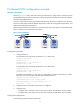
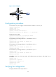
Super VLAN configuration example
Network requirements
As shown in Figure 7:
• Create super VLAN 10, and configure its VLAN interface IP address as 10.0.0.1/24.
• Create sub-VLANs VLAN 2, VLAN 3, and VLAN 5.
• Assign Ethernet 1/1 and Ethernet 1/2 to VLAN 2, Ethernet 1/3 and Ethernet 1/4 to VLAN 3, and
Ethernet 1/5 and Ethernet 1/6 to VLAN 5.
• The sub-VLANs are isolated at Layer 2 but connected at Layer 3.